


4D68 ENGINE (E- W) -
Cylinder Head, Valves and Valve Springs
11A-9-6
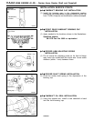
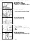
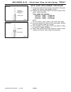
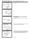
(2) Install the valve and, while pressing the valve against
the valve seat, measure the valve stem projection between
the valve stem end and the valve spring seat seating
surface.
Standard value: 43.45 mm
Limit: 43.95 mm
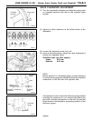
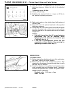
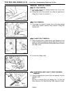
VALVE SEAT RECONDITIONING PROCEDURE
(1) Before correcting the valve seat, check the clearance
between the valve guide and valve. If necessary, replace
the valve guide.
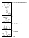
(2) Using the appropriate special tool or seat grinder, correct
the valve seat to achieve the specified seat width and
angle.
(3) After correcting the valve seat, lap the valve and valve
seat using lapping compound. Then, check the valve stem
projection (refer to 5. VALVE SE AT in INSPECTION).
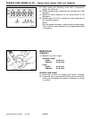
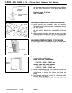
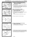
VALVE SEAT REPLACEMENT PROCEDURE
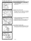
(1) Cut the valve seat to be replaced from the inside to thin
the wall thickness. Then, remove the valve seat.
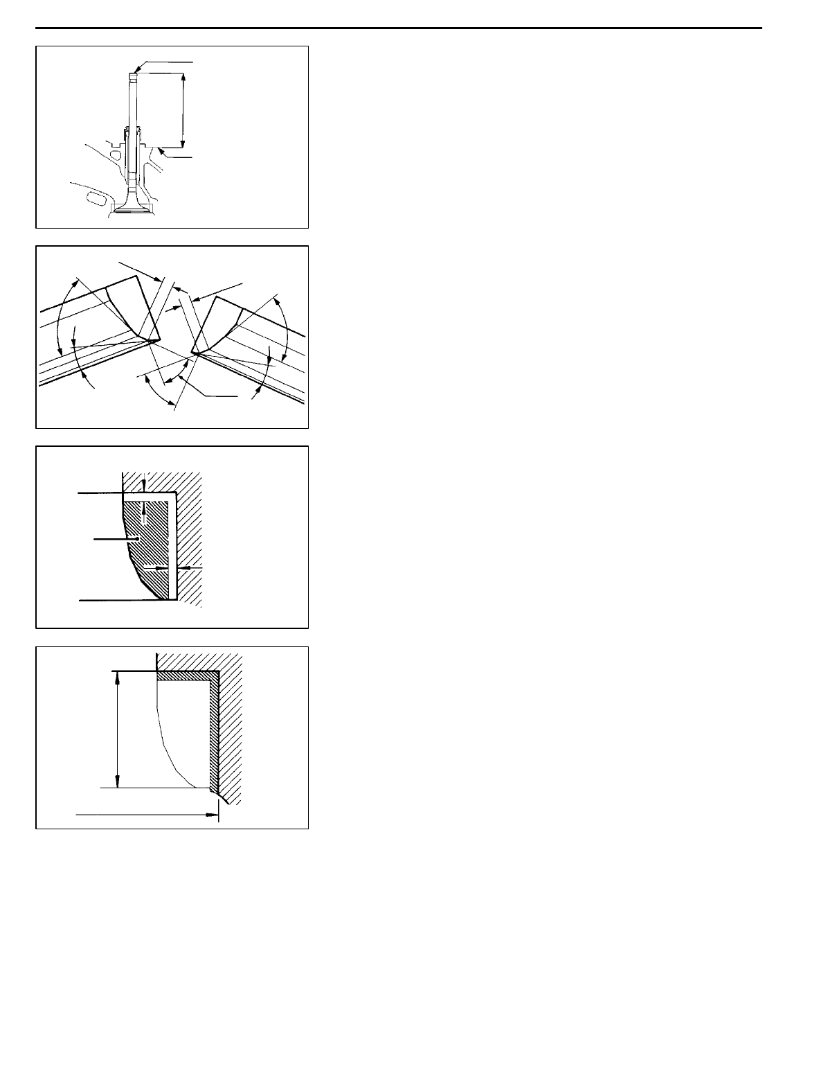
(2) Rebore thevalveseat holeinthe cylinderhead toaselected
oversize valve seat diameter.
Intake valve seat hole diameter
0.30 O.S.: 38.300 - 38.325 mm
0.60 O.S.: 38.600 - 38.625 mm
Exhaust valve seat hole diameter
0.30 O.S.: 34.300 - 34.325 mm
0.60 O.S.: 34.600 - 34.625 mm
(3) Before fitting the valve seat, either heat the cylinder head
up to approximately 25 0°C or cool the valve seat using
cooling spray, t o prevent the cylinder head bore from
galling.
(4) Using a valve seat cutter, correct the valve seat to the
specified width and angle.
See “VALVE SEAT RECONDITIONING PROCEDURE”.
PWEE9609
E
Dec. 1996Mitsubishi Motors Corporation
DEN0212
Valve stem end
Valve stem
projection
Spring seat seating
surface
1EN0105
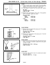
0.9 - 1.3 mm
0.9 - 1.3 mm
65
°
15
°
44
°
44
°
15
°
65
°
1EN0274
0.5 - 1.0 mm
0.5 - 1.0 mm
Cut
away
1EN0275
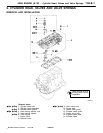
Height of
seat ring
Oversize I.D.