


4D68 ENGINE (E- W) -
Cylinder Head, Valves and Valve Springs
11A-9-3
"
C
A
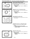
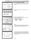
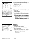
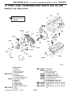
RETAINER LOCK INSTALLATION
(1) The valve spring, if excessively compressed, causes the
bottom end of the retainer to be in contact with, and
damage, the stem seal.
"
D
A
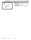
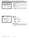
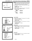
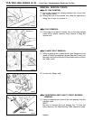
CYLINDER HEAD GASKET INSTALLATION
(1) In case any of the cylinder block, piston, connecting rod
and crankshaft has not been replaced, install the gasket
of the same rank as before which can be identified by
the mark shown in the illustration at left.
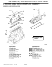
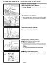
(2) In case any of the cylinder block, piston, connecting rod
and crankshaft have been replaced, reselect and install
the gasket in accordance with the following procedure.
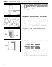
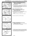
1 With each piston held at the top dead center, measure
its protrusion from the upper block surface at the
locations shown in the illustration at left (total of eight
locations). Be sure to take measurements on the
crankshaft center line.
2 Using the average of the eight measurements, select
the gasket rank (A, B or C) in accordance with the
table given below. If, however, the maximum protrusion
at any one location exceeds the protrusion tolerance
shown for any rank in the following table, use the
gasket one rank higher that rank.
mm
Rank
Average value
of piston
protrusions
Protrusion
tolerance for
each rank
Thickness of
selected gasket
(when tightened)
A 0.641 - 0.700 0.750 1.40
±
0.05
B 0.700 - 0.760 0.810 1.45
±
0.05
C 0.760 - 0.823 - 1.50
±
0.05
"
E
A
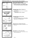
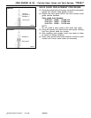
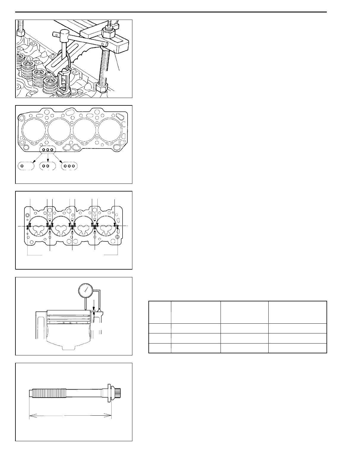
CYLINDER HEAD BOLT INSTALLATION
(1) When installing the cylinder head bolts, check that the
shank length of each bolt meets the limit. If the limit is
exceeded, replace the bolt.
Limit: max. 119.7 mm
(2) Apply engine oil to the bolt threads and washers.
PWEE9609
E
Dec. 1996Mitsubishi Motors Corporation
DEN0779
MD998772
DEN0796
Identification mark
Rank A Rank B Rank C
DEN0797
12345678
Protrusion measuring locations
(with each piston attop dead center)
Reference for measurement
DEN0798
Protrusion
6EN0782
Shank length