


4D68 ENGINE (E- W) -
Pistons and Connecting Rods
11A-11-2
REMOVAL SERVICE POINTS
A
A
"
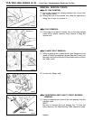
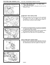
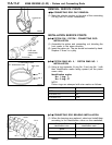
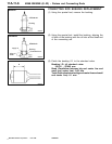
CONNECTING ROD CAP REMOVAL
(1) Mark the cylinder number on the side of the connecting
rod big end for correct reassembly.
INSTALLATION SERVICE POINTS
"
A
A
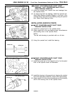
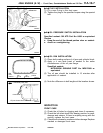
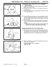
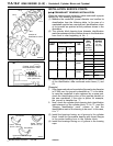
PISTON PIN / PISTON / CONNECTING ROD
INSTALLATION
(1) Assemble the piston and connecting rod, directing the
front marks in t he same direction.
(2) Insert the piston pin. The pin should be inserted by hand.
Replace if there is a play.
"
B
A
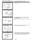
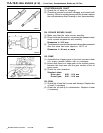
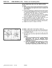
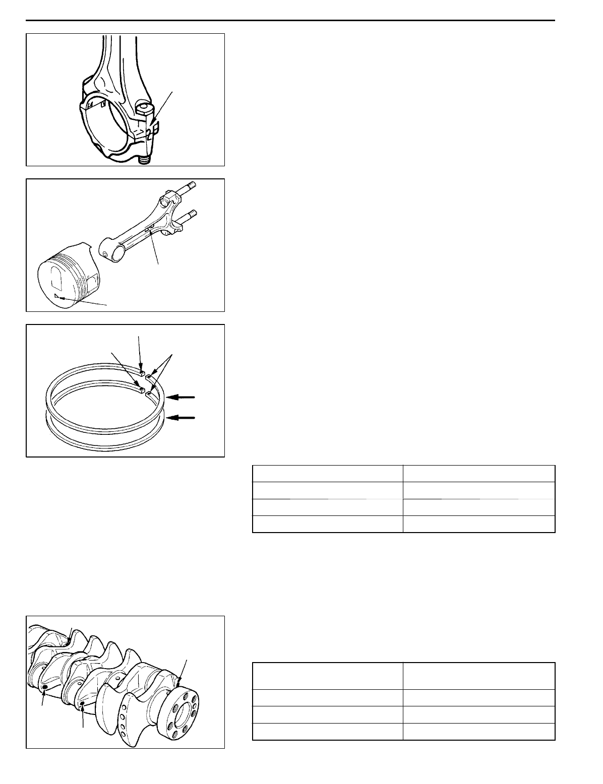
PISTON RING NO. 2 / PISTON RING NO. 1
INSTALLATION
(1) Using a ring expander, fit ring No. 2 a n d ring No. 1 with
their identification marks facing upward (on the piston
crown side).
Identification marks:
No. 1 ring: T
No. 2 ring: 2T
NOTE
Piston rings are stamped with size marks as follows:
Size Size mark
STD None
0.50 mm O.S. 50
1.00 mm O.S. 100
"
C
A
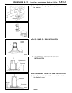
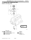
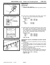
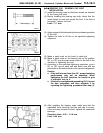
CONNECTING ROD BEARING INSTALLATION
(1) When the bearings are replaced, select a nd install them
according to the identification colors on the crankshaft.
Crank pin O.D.
identification color
Connecting rod bearing
identification mark
Yellow 1
None 2
White 3
PWEE9609
E
Dec. 1996Mitsubishi Motors Corporation
DEN0050
Cylinder No.
DEN0784
Front mark
Front mark
(Identification
mark)
9EN0524
“T” identification mark
“2T” identification mark
Side mark
No. 1
No. 2
6EN0700
Location of identification
colors
No. 1
No. 2
No. 3
No. 4