


X
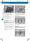
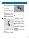
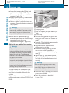
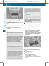
Ensure that clamping claw A sits flush
against the inner edge of roof rail F.
If necessary, adjust the span width of the
crossbar (Y page 276).
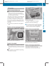
X
Slightly tighten up bolts ? on both sides
in a clockwise direction.
X
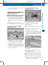
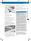
Tighten up bolts ? on the front and rear
crossbars. Observe the tightening torque of
4 lb/ft (6 Nm) .
G
Warning!
Have the tightening torque checked after
mounting the crossbars. The screws could
come loose if they are not tightened to a
torque of 4 lb-ft (6 Nm).
X
Attach and lock protective caps ;.
X
Stow the key and Allen key in the stowage
compartment under the cargo
compartment floor again (Y page 274).
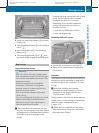
Setting the span width of the crossbars
G
Warning!
Only install the crossbars at the exact
locations designated on the roof rails. The
designated locations for the front crossbars
are between the markings engraved on the
inside of the roof rails. The designated
locations for the rear crossbars are between
the gaps on the roof rails.
Otherwise, the crossbars, mounted
accessories and the objects attached to them
could come loose from the vehicle causing an
accident, thereby injuring you and other
persons and/or causing damage to property,
including damage to your vehicle.
The span width of the crossbars for your
vehicle is set at the factory. The span widths
only fit in the intended positions on the
vehicle.
Only install the crossbars at the marked
positions and observe stickers = FRONT and
REAR.
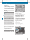
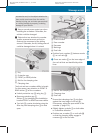
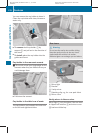
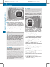
?
Bolt for the clamping claw
A
Clamping claw
G
Bolts for adjusting the span width (2 per
side)
H
Cover strip
X
Pull cover strip H out of the groove until
bolts G on both ends of the crossbar are
visible.
X
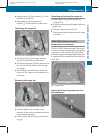
Turn bolts G on both sides approximately
two turns counterclockwise.
X
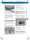
Align the crossbars on the marked
positions on the roof rails.
X
Ensure that clamping claws A sit flush
with the roof rails on both sides. If
necessary, pull out or slide into clamping
claws A.
X
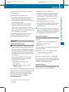
Tighten bolts G. Observe the tightening
torque of 4 lb/ft (6 Nm) .
The width of the clamping claw is not set
correctly.
G
Warning!
Have the tightening torque checked after
mounting the crossbars. The screws could
come loose if they are not tightened to a
torque of 4 lb-ft (6 Nm).
X
Press cover strip H piece by piece into the
groove of the crossbar.
X
Install the crossbars as described
(Y page 274).
276
Stowage areas
Loading, stowing and features
BA 164.8 USA, CA Edition B 2011; 1; 2, en-US
d2sboike Version: 3.0.3.5
2010-04-21T15:08:44+02:00 - Seite 276