


32
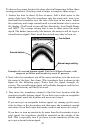
If the base of the transom has a radius, fill the gap between the tran-
som and the sensor with the sealant. This will help ensure a smooth
water flow.
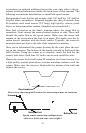
Route the sensor's cable through or over the transom to the sonar unit.
If you need to drill a hole in the transom to pass the connector through,
the required hole size is 7/8".
CAUTION:
If you drill a hole in the transom for the cable, make sure it is lo-
cated above the waterline. After installation, be sure to seal the
hole with the same marine grade above- or below-waterline seal-
ant used for the screws.
The sensor is now ready for use. Connect the sensor to the sonar socket
on the back of your unit and connect the transducer to the speed sensor's
socket (see drawing on page 41). If you have any questions concerning
the installation of the sensor, please contact your local boat dealer.
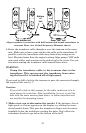
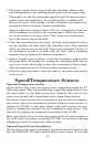
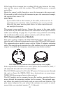
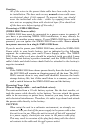
GPS Antenna/Receiver Module
This unit's package includes the LGC-2000 GPS module. This device con-
tains the unit's external antenna and receiver for GPS and WAAS signals.
The antenna/receiver module comes with a 25-foot Y-adapter extension
cable. This module can be mounted on a flat surface or pole, or an optional
magnet is available for temporary mounting on any ferrous surface.
LGC-2000 Module, bottom view (left) and top view (right).
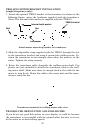
Tools required for installation are: wire pliers, flat screwdriver, drill, 1"
(25 mm) drill bit and 3/16" (4.75 mm) drill bit.
The LGC-2000 requires 9 to 20 volts DC power. It draws power through
the unit or from the NMEA 2000 buss (instructions on powering a
NMEA 2000 buss appear later in this section).
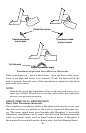
The GPS module can be mounted on any flat surface, provided there is
access behind the mounting surface for the screws. The optional mag-
net allows the module to be easily used on cars or off-road vehicles. The
pole mount adapter lets you mount the antenna on a pole or swivel
mount that uses standard marine 1" - 14 threads.