


1
2
3
4
5
5
6
7
S
8
9
6-3E
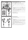
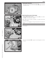
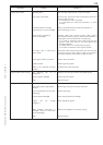
– Wrap insulating tape around the output shaft in the area of the sharp
edge
1 to prevent the seal shaft ring from being damaged.
NOTE: wrap insulating tape just above edge to allow the tape to be
easily pulled off after the seal shaft ring is mounted.
– Grease the seal lip and press in the seal shaft ring.
– Pull off the tape.
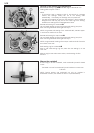
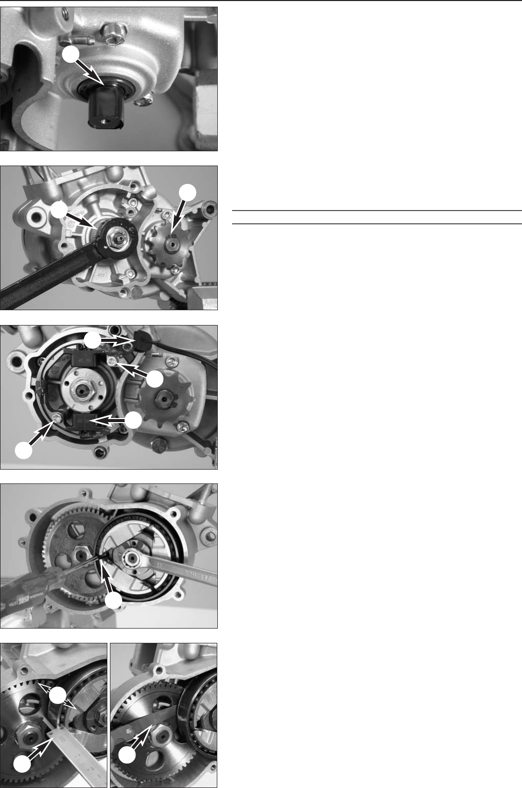
Mounting the ignition
– Place woodruff key in the crankshaft groove.
– Mount ignition rotor
2 with a washer, holding back with special tool,
secure nut with Loctite 243 and tighten to 20 Nm (15 ft.lb).
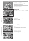
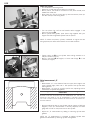
!
CAUTION
!
THE PINS ON THE SPECIAL TOOL MAY NOT ENGAGE IN THE ROTOR'S THREADED
HOLES
, OTHERWISE THE THREAD WILL BE DAMAGED.
– Slide the chain sprocket
3 on the output shaft with the collar
towards housing and mount the circlip.
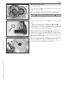
– Mount ignition stator
4 in the case.
NOTE: for easier installation, gently press the stator together with your
fingers. Check for a correct fit prior to bolting tight, stator may not
cant.
– Secure allan bolts M5x25
5 on the stators with Loctite 243 and
tighten to 8 Nm (6 ft.lb).
– Position cable guide
6.
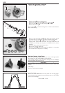
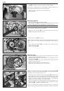
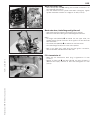
Mount the clutch
– Slide spacing washer(s) (25x15) onto the crankshaft, mount needle
bearings and the centrifugal clutch unit.
– Block the centrifugal clutch, drum and gear of the primary drive with
a suitable mandrel
7.
– Secure the nut M10x1.25 on the crankshaft with Loctite 243 and
tighten to 35 Nm (25 ft.lb).
– Tighten the output shaft nut to 40 Nm (30 ft.lb).
– Bend over the lock washer on the output shaft nut.
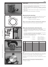
NOTE: for a correct function of the centifugal clutch axial clearance
S
between 0,2 and 0,7 mm (0,039 and 0,0055 in) must remain between
the bottom of the drum and the clutch unit.
– Checking the axial clearance with a sliding gauge
8 by pressing the
drum against the spacer and measure the distance from the upper
edge of the drum to the drive wheel.Then pull the drum against the
clutch unit, hold in position and measure again - the difference
between these measurements is the axial clearance.
– Press drum against the spacing washers by hand and measure the
distance between the drum and the gear of the primary drive using a
feeler gauge
9 - it should be at least 0.5 mm.
NOTE: if the clearances are outside of the tolerance zone, use spacing
washers to balance. Spacing washers are available in different thicknesses.