


Operation
CZ76372,00001DE 1912OCT102/2
PC11899—UN—01APR09
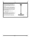
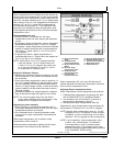
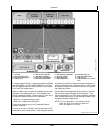
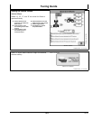
GreenStar—Guidance
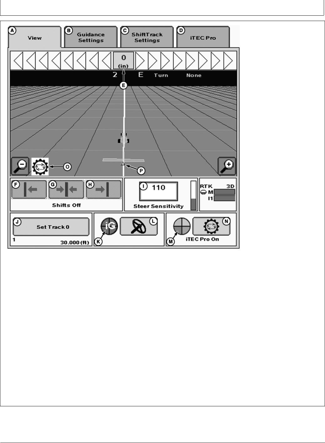
A—View Tab
B—Guidance Setting Tab
C—Shift Track Settings Tab
D—iTEC Pro Tab
E—Path Accuracy Indicator
F—Shift Track Left Button
G—Shift Track Center Button
H—Shift Track Right Button
I— Steer Sensitivity InputBox
J— Set Track 0 Button
K—iGuide Status Pie
L—Steer On/Off button
M—iTEC Pro Status Pie
N—iTEC Pro Enable Button
O—iTEC Pro Icon
P—Implement Receiver Location
Icon
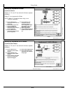
In order to operate iGuide, a valid setup must be available
(see APPENDIX—VALID CONFIGURATION). AutoTrac
can be engaged when the “steering wheel” icon is visible
in the AutoTrac enable button.
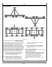
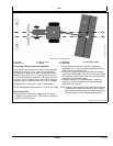
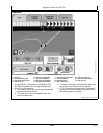
While in iGuide mode, machine and implement icons are
displayed in the perspective view. The implement will
have the guidance triangle. The error bar (D) at the top of
the page will display the error at the implement.
•
Blue line—recorded implement path
•
White line—implement tracking line
For all other settings refer to the GreenStar Display
operator’s manual.
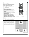
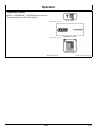
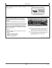
If iGuide is not set up correctly, the AutoTrac steer on/off
button will be shown as a wrench. If the diagnostic wrench
is pressed, the AutoTrac diagnostic pages will appear to
indicate which items are not properly set up. Once iGuide
is properly configured, the steer on/off button will replace
the diagnostic wrench.
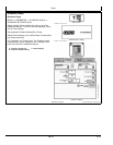
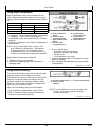
When the AutoTrac diagnostic wrench button is selected,
the AutoTrac diagnostic page will be displayed. If the
valid configuration is not valid, select implement guidance
from the dropdown menu on the diagnostic page to view
implement guidance diagnostics.
NOTE: For Line acquisition, the vehicle must be
within the 40% of the tracking width and
within 80 degrees of the line.
202
102110
PN=35