


Setup
CZ76372,00001DC 1912OCT102/3
CZ76372,00001DC 1912OCT103/3
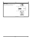
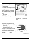
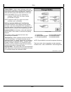
InLine distance from nonsteering axle to GPS receiver
(B) will be
•
Row crop tractors—rear axle
•
Articulated tractors—front axle
•
Track tractors—rear axle
NOTE: Offset (B) for track tractors should be measured
from the receiver to the pivot point.
Offset Toggle button (E) toggles the receiver from the left
side of machine to the right side.
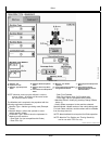
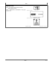
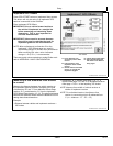
Verify that the correct connection point is selected and
measure from the center of nonsteering axle to the
center of connection point (Example: center of drawbar
pin or lower links, except in the case of a rear pivot 2pt
mount—measure to the pivot point of the implement
tongue).
NOTE: Offset (C) will change when the connection
point changes.
IMPORTANT: Offsets must be accurate because they
will be used to calculate the guidance
path for iGuide.
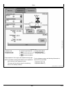
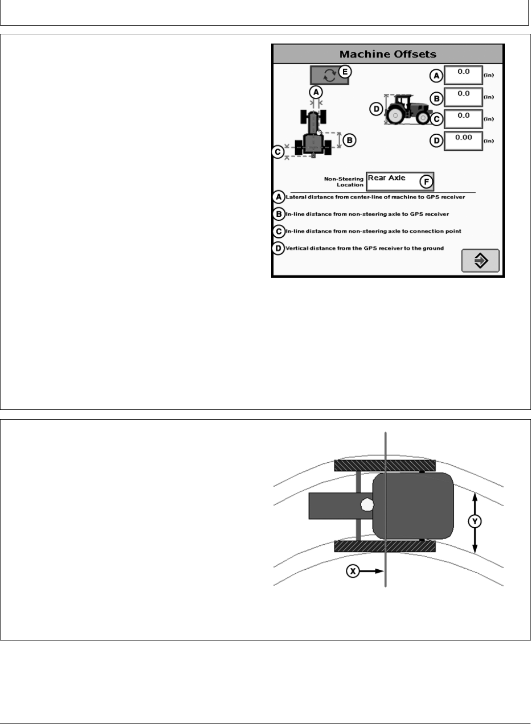
PC11898—UN—01APR09
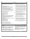
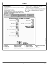
Machine Offsets
A—Lateral distance from
centerline of machine to
GPS receiver
B—Inline distance from
nonsteering axle to GPS
receiver
C—Inline distance from
nonsteering axle to
connection point
D—Vertical distance from the
GPS receiver to the ground
E—Offset Toggle Button
F—NonSteering Location
DropDown Menu
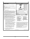
Machine Offsets—The machine and implement offsets
are important for implement guidance to function properly.
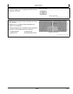
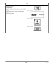
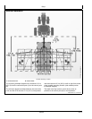
1. On Track machines, the nonsteering axle should be
selected as rear axle.
2. Offsets B and C should be measured to the turning
point or pivot point of the machine. For example: when
turning machine, it usually does not rotate on the rear
axle but somewhere in front of the rear axle.
This dimension can be measured by turning the machine
in a fairly tight turn, such as an end turn. Stop half way
through the turn. Looking at the inside track and its
relationship to the tracks on the ground, determine the
pivot point of the machine. Vehicle ballasting and drawbar
load could affect these offsets.
X—Pivot Point Y—Tractor Tracks
PC11205—UN—14JUL08
Track Machines
155
102110
PN=18