


Electrical
Input voltage
10 VDC to 40 VDC, reverse polarity protected
Input current (GPS navigation input)
500 mA typical, 750 mA max at 13.75 VDC
250 mA typical, 375 mA max at 27.5 VDC
Input current (comm input - GX60/65 only)
270 mA typical, 2A max at 13.75 VDC, receive
130 mA typical, 900 mA max at 27.5 VDC, receive
2.1A typical, 3.2A max at 13.75, transmit
1.0A typical, 1.4A max at 27.5 VDC, transmit
Input power (GPS navigation input)
7 watts typical
Input power (comm input - GX60/65 only)
3.7 watts typical, receive
28 watts typical, transmit
GX50 and GX60/65 Avionics Outputs
CDI L/R deviation ±150 mv full scale
TO/OFF/FROM flag ±250 mv, TO/FROM indication
Nav valid flag +300 mv for valid indication
Nav superflag 400 ma source
VDI up/down ±150 mv
VDI valid flag +300 mv
VDI superflag 400 ma source
Annunciators
MSG (message)
PTK (parallel track)
OBS/HLD (waypoint sequencing hold)
GX50/60 only
APPRCH (approach enabled)GX50/60 only
ACTIVE (approach active) GX50/60 only
GX55 Avionics Outputs
CDI L/R deviation ±150 mv full scale
TO/OFF/FROM flag ±250 mv, TO/FROM indication
Nav valid flag +300 mv for valid indication
Annunciators
MSG (message)
PTK (parallel track)
Avionics Inputs
Serial
Frequency flip/flop (GX60/65 only)
Waypoint Sequence (GX50/60 only)
1-10
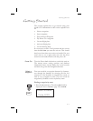
Apollo GX Features