


SOLID STATE ECONOMIZER SYSTEM
9 63-2484—2
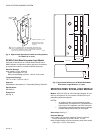
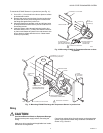
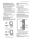
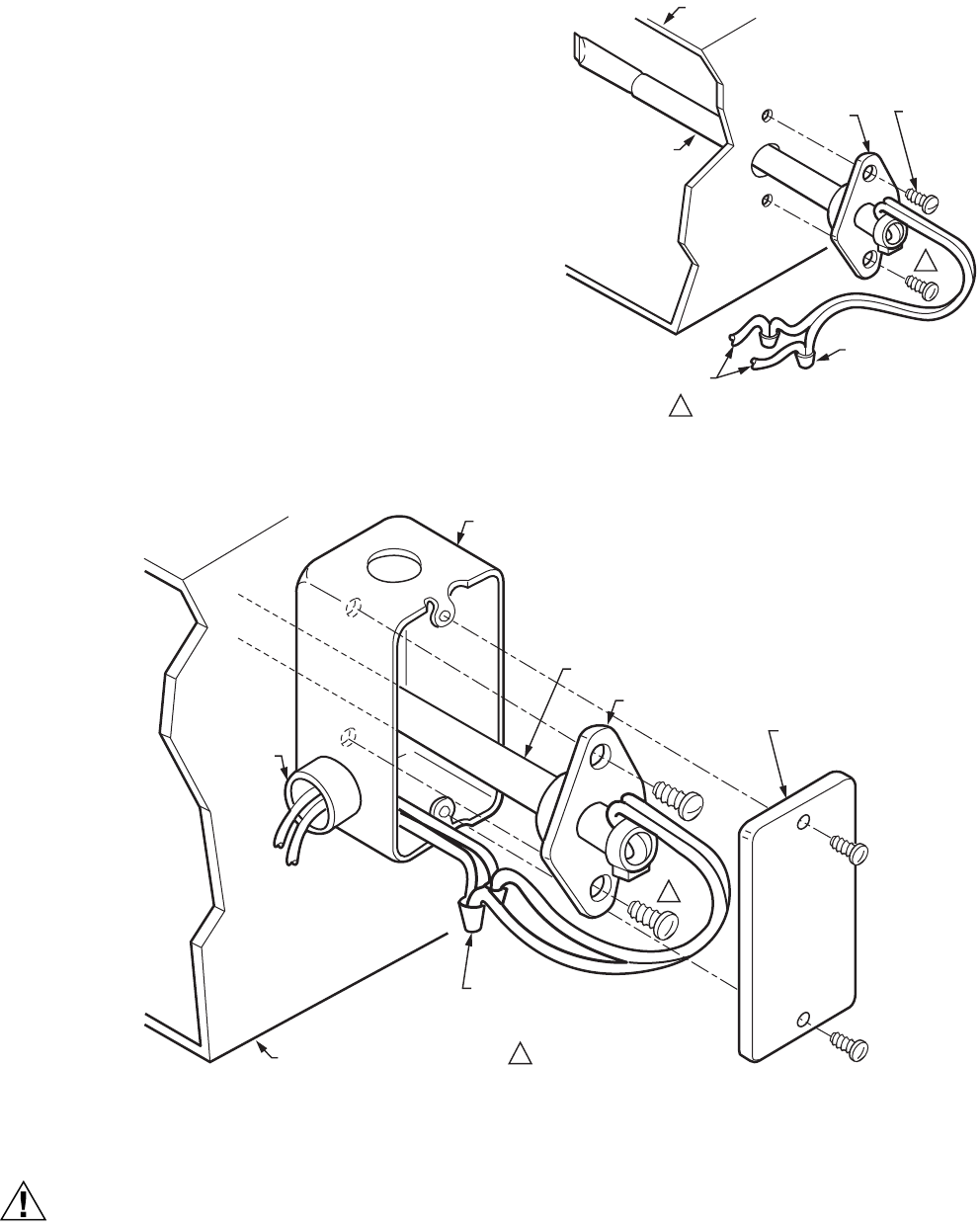
To mount the C7046C Sensor in a junction box (see Fig. 11):
1. Cut a 1/2 in. (13 mm) hole in the duct or plenum surface
at the desired location.
2. Remove the center rear knockout from the junction box
and insert the sensor probe through the knockout with
the flange flat against the junction box.
3. Using the flange as a template, mark and drill two holes
in the junction box and the duct or plenum surface for no.
8 mounting screws.
4. Insert the sensor probe through both the junction box
knockout and the 1/2 in. (13 mm) hole drilled in the duct
or plenum and fasten the junction box and sensor to the
duct or plenum surface with the two no. 8 sheet metal
screws (not provided).
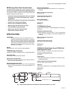
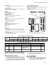
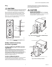
Fig. 10. Mounting C7046C Air Temperature Sensor on duct
or plenum.
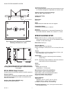
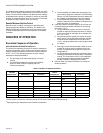
Fig. 11. Mounting C7046C Discharge Air Temperature Sensor in junction box.
Wiring
CAUTION
Can Cause Electrical Shock or Equipment Damage.
Disconnect the power supply before connecting the
wiring.
Make sure wiring complies with applicable local codes,
ordinances and regulations.
Connect low voltage wiring from the sensor to the appropriate
system component terminals using solderless connectors as
shown in Fig. 10 and 11.
SCREWS NOT PROVIDED.1
SENSOR PROBE
SYSTEM DUCT OR PLENUM
FLANGE
NO. 8
MOUNTING
SCREWS (2)
TO APPROPRIATE
SYSTEM COMPONENTS
(SEE WIRING DIAGRAM)
SENSOR WIRES WITH
2 SOLDERLESS
CONNECTORS
1
M9086
SCREWS NOT PROVIDED.1
1
SENSOR PROBE
SYSTEM DUCT OR PLENUM
FLANGE
STANDARD 2 X 4 (51 X 102)
OUTLET BOX (OPTIONAL)
CONNECTOR
AND
LOCKNUT
BLANK
FACEPLATE
(OPTIONAL)
TO APPROPRIATE
SYSTEM COMPONENTS
(SEE WIRING DIAGRAM)
SENSOR WIRES WITH 2
SOLDERLESS CONNECTORS
M9088