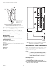
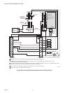
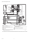
SOLID STATE ECONOMIZER SYSTEM
19 63-2484—2
7. If all minimum and maximum position adjustments are
complete, remove the T-T1 jumper and reconnect the
mixed air sensor.
EQUATION 1. FORMULA TO AID MINIMUM POSITION ADJUSTMENT.
(T
O
× OA)+(T
R
× RA)= T
M
Where:
T
O
= Outdoor air temperature
OA = Percent of outdoor air
T
R
= Return air temperature
RA = Percent of return air
T
M
= Resulting mixed air temperature
NOTE: The following sample calculation uses only Fahren-
heit temperature.
EXAMPLE: Assume local codes require 10% outdoor air dur-
ing occupied conditions, outdoor air is 60°F and
return air is 75°F. Under these conditions, what is
the temperature of the mixed air?
(0.1 × 60°F)+(0.9 × 75°F)=6.0°F + 67.5°F=73.5°F
Mixed air will be 73.5°F when OA is 60°F and RA is 75°F with
10 percent outdoor air entering the building.
DCV Maximum Position Adjustment
1. Disconnect mixed air sensor from terminals T and T1
and short terminals T and T1.
2. Connect a jumper between terminals AQ and AQ1.
3. Connect 24 Vac across terminals TR and TR1.
4. Adjust the potentiometer on the face of the device with a
small screwdriver for desired maximum position.
5. If all minimum and maximum position adjustments are
complete, remove the T-T1 jumper and reconnect the
mixed air sensor.
Enthalpy Changeover Setpoint
Outdoor Enthalpy Changeover Setpoint
(Single Enthalpy)
The outdoor enthalpy changeover setpoint returns the outdoor
air damper to minimum position when enthalpy rises above its
setpoint. Enthalpy setpoint scale markings, located in the
device, are A, B, C and D. See Fig. 18 for the corresponding
control point. The factory-installed 620-ohm jumper must be in
place across terminals SR and SR+. Temperature and humidity
points to the left of the selected curve will allow the dampers to
open for free cooling.
Differential Enthalpy Changeover Setting
Differential enthalpy control uses two C7400 Enthalpy Sensors
connected to one logic module. The logic module compares
outdoor air to return air.
NOTE: Turn the enthalpy setpoint potentiometer fully clock-
wise to the D setting.
The logic module selects the lower enthalpy air (return or
outdoor) for cooling. For example, when outdoor air has lower
enthalpy than return air, the module calls to open the outdoor
air damper to bring in outdoor air for free cooling.
Exhaust Setpoint
The exhaust setpoint determines when the exhaust fan runs
based on damper position. When the exhaust fan call is made,
the module provides a 60 ±30 second delay before exhaust fan
activation. This delay allows the damper to reach the
appropriate position to avoid unnecessary fan overload.
NOTES:
— EF and EF1 are 24V dry contacts only. An external
line voltage contactor is required to operate the
exhaust fan.
— When the exhaust fan is deactivated the EF and
EF1 contacts open immediately.
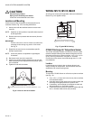
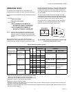
CHECKOUT AND TROUBLESHOOTING
Tables 6 through 10 provide step-by-step economizer checkout
and troubleshooting steps. See Fig. 23 and 25 for enthalpy
setpoint potentiometer, minimum position potentiometer and
LED locations.
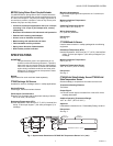
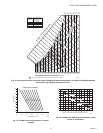
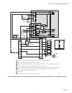
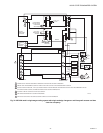
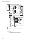
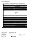
Fig. 26. Meter location for checkout and troubleshooting.
1
1
2
2
M9097
ENTHALPY CHANGEOVER
SETPOINT
LED LIGHTS WHEN
OUTDOOR AIR IS SUITABLE
FOR FREE COOLING
INSERT DC MILLIAMMETER BETWEEN S
O
AND S FOR CHECKOUT
AND TROUBLESHOOTING.
JUMPER USED FOR SINGLE ENTHALPY CONTROL.
TR
TR1
A
BC
D
S
O
S
R
+
+
+
C7400
620 OHM
JUMPER
DC
MILLIAMMETER
W7459
S
+