


Automation and Control Solutions
Honeywell International Inc. Honeywell Limited-Honeywell Limitée
1985 Douglas Drive North 35 Dynamic Drive
Golden Valley, MN 55422 Toronto, Ontario M1V 4Z9
customer.honeywell.com
SOLID STATE ECONOMIZER SYSTEM
® U.S. Registered Trademark
© 2005 Honeywell International Inc.
63-2484—2 M.S. Rev. 08-06
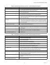
4. DCV AND EXHAUST
Execute step one, Checkout Preparation. –
Ensure terminals AQ and AQ1 are open. LED for both DCV and Exhaust should be off.
Actuator drives fully closed.
Connect 9V battery positive to AQ and negative to AQ1. LED for both DCV and Exhaust turn on.
Actuator drives to between 81 and 85 degrees open.
Turn Exhaust potentiometer CW until Exhaust LED turns
off.
Exhaust LED turns off with potentiometer approximately 90
percent CW. Actuator remains in position.
Turn DCV setpoint potentiometer CW. DCV LED turns off with potentiometer at approximately 9V.
Actuator drives fully closed.
Turn DCV setpoint potentiometer CCW until Exhaust LED
turns on.
Exhaust contacts close 30-90 seconds after Exhaust LED
turns on.
Turn DCV setpoint potentiometer CW. Exhaust LED turns off with potentiometer indication at
approximately 9V.
Turn Exhaust potentiometer CCW until Exhaust LED turns
on.
Exhaust contacts close 30-90 seconds after Exhaust LED
turns on.
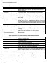
5. MINIMUM AND MAXIMUM POSITION
Execute step one, Checkout Preparation. –
Connect 9V battery positive to AQ and negative to AQ1. DCV LED turns on. Actuator drives to between 81 and 85
degrees open.
Turn DCV maximum position potentiometer to midpoint. Actuator drives to between 18 and 72 degrees open.
Turn DCV maximum position potentiometer to fully CCW. Actuator drives fully closed.
Turn minimum position potentiometer to midpoint. Actuator drives to between 18 and 72 degrees open.
Turn minimum position potentiometer fully CW. Actuator drives fully open.
W7212: Remove jumper from TR and N. Actuator drives fully closed.
6. MIXED AIR INPUT
Execute step one, Checkout Preparation. –
Set enthalpy potentiometer to A. Free cool LED turns on.
Actuator drives to between 18 and 72 degrees open.
Remove 5.6K ohm resistor and jumper from T and T1. Actuator drives fully open.
Remove jumper from T and T1 and leave open. Actuator drives fully closed.
7. HEAT PUMP INPUT - W7213, W7214 ONLY
Execute step one, Checkout Preparation. –
Set enthalpy potentiometer to A. Free cool LED turns on.
Actuator drives to between 18 and 72 degrees open.
W7213: Jumper TR to B.
W7214: Remove jumper from TR and O.
Free cool LED turns off.
Actuator drives fully closed
Table 10. Checkout for W7212, W7213, W7214 Economizers Connected to Honeywell Actuator. (Continued)
Step Checkout Procedure Proper Response