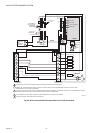
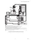
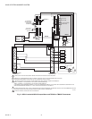
SOLID STATE ECONOMIZER SYSTEM
63-2484—2 18
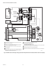
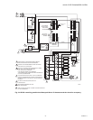
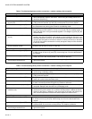
NOTES:
— DCV and Free Cooling have setpoints and LED indications.
— For models with a B terminal (W7213):
No power to B: cooling mode, free cool enabled. Module follows logic detailed above.
24V power to B: heating mode, free cool disabled. Actuator drives to minimum position (closed when Unoccupied).
— For models with an O terminal (W7214):
24V power to O: cooling mode, free cool enabled. Module follows logic detailed above.
No power to O: heating mode, free cool disabled. Actuator drives to minimum position (closed when Unoccupied).
SETTINGS AND ADJUSTMENTS: W7212
CAUTION
Equipment Damage Hazard.
Excessive force can damage potentiometer
controls.
Use a small screwdriver when adjusting enthalpy
changeover and minimum damper position controls.
Potentiometers with small screwdriver adjustment slots,
located on device face, provide adjustments for several
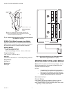
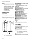
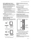
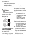
parameters (see Fig. 25 for locations on device):
— DCV setpoint.
— Minimum damper position.
— DCV maximum damper position.
— Enthalpy changeover.
— Exhaust setpoint.
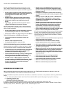
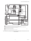
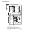
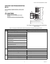
Fig. 25. Potentiometer and LED locations (W7212 shown).
Demand Control Ventilation Setpoint
The logic module modulates the outdoor damper to provide
ventilation based on the 0/2-10 Vdc DCV. With no cooling
signal, the DCV overrides the outdoor air damper when
ventilation requires additional outdoor air.
Adjusting Minimum and Maximum Positions
The minimum position potentiometer maintains the minimum
outdoor air flow into the building during the occupied period.
The minimum position allows for the building effluents. The
DCV maximum position potentiometer allows the installer to
limit the amount of outdoor air flow into the building when the
DCV overrides the mixed air sensor and allows the proper
ventilation based on occupancy. Setting the DCV maximum
position of the damper prevents the introduction of large
amounts of hot or cold air into the space by preventing the
dampers from opening 100%. Set the DCV maximum position
at the maximum design occupancy.
IMPORTANT
With the DCV maximum position set below the mini-
mum position, the minimum position overrides the
maximum position (negating most DCV functions of
the logic module, as the damper cannot move).
NOTES:
— When the mixed air sensor takes control based on
an increased requirement for cooling, it overrides
the DCV maximum position potentiometer and can
drive the damper full-open.
— If the mixed air temperature drops to 45°F, the
mixed air sensor overrides the DCV and fully
closes the damper to protect from freezing the hot
or chilled water coils. Control returns to normal
once the mixed air temperature rises to 48°F.
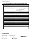
Minimum Position Adjustment
For detailed assistance in minimum position selection
reference the Economizer Application Guide (form 63-8594)
Ventilation section. The following provides basic guidelines for
minimum position selection and adjustment:
IMPORTANT
• Adjust the minimum position potentiometer to allow
the minimum amount of outdoor air for building efflu-
ents, as required by local codes, to enter the building.
• This procedure requires use of a quality thermometer
capable of reading to 0.5°F (0.25°C).
NOTE: Make minimum position adjustments with at least a
10°F (6°C) temperature difference between outdoor
and return air.
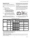
1. Calculate the appropriate mixed air temperature. See
Equation 1.
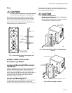
2. Disconnect mixed air sensor from terminals T and T1.
3. Place a jumper across terminals T and T1.
4. Ensure that either the factory-installed jumper is in place
across terminals P and P1 or, if remote damper position
is required, that it is wired according to Fig. 24 and
turned fully clockwise.
5. Connect 24 Vac across terminals TR and TR1.
6. Carefully adjust the potentiometer on the face of the
device with a small screwdriver until the mixed air tem-
perature reaches the calculated value.
NOTE: Ensure that the sensed air is well-mixed.
DEMAND CONTROL
VENTILAION SETPOINT
ENTHALPY
CHANGEOVER SETPOINT
LED LIGHTS WHEN
DEMAND CONTROL
VENTILAION INPUT
IS ABOVE SETPOINT
EXHAUST
FAN SETPOINT
LED LIGHTS
WHEN EXHAUST
CONTACT IS MADE
MINIMUM DAMPER
POSITION SETTING
M20604
N1
P1
T1
N
2V
2V
2V
B
A
SR
SO
AQ
C
D
Free
Cool
10V
EXH
DCV
EXH
Set
10V
DCV
Max
10V
DCV
Set
Min
Pos
Open
P
T
AQ1
SO+
SR+
MAXIMUM DAMPER
DEMAND CONTROL
VENTILATION SETPOINT
LED LIGHTS WHEN
OUTDOOR AIR IS
SUITABLE FOR
FREE COOLING