


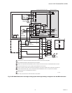
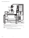
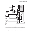
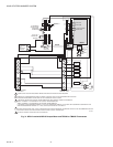
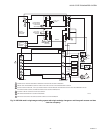
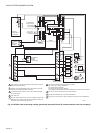
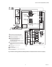
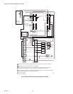
SOLID STATE ECONOMIZER SYSTEM
63-2484—2 30
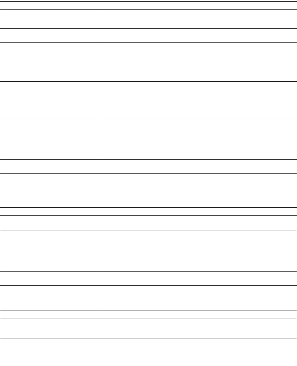
Table 8. Troubleshooting three-position economizer—outdoor enthalpy above setpoint.
Condition on Logic Module Should Be Conditions Not Met
1. Red LED not lighted. 1. If the LED glows, the module is in the economizer mode. Verify the conditions are
above the enthalpy setpoint, see Note 2. Check wiring to Enthalpy Control for a
short from {SO} and {+}.
2. 24 Vac to terminals {TR} and {TR1},
{X} and {TR}.
2. Check the wiring from [G] and [C] on the unit low voltage terminal strip. {TR} and
{TR1} power the actuator. {X} and {TR} provide power for minimum position.
3. 24 Vac to terminals {1} and {TR}. 3. Verify that there is a call for cooling from the thermostat. Without a call for cooling
the compressor can not be in the normal air conditioning mode.
4. 24 Vac to terminals {2} and {TR}. 4. If 24 Vac is not on {2} and {TR}, the internal contacts are not set correctly. Remove
the {SO} wire from the module. If 24 Vac is on {2} and {TR}, the enthalpy control is
bad or the {SO} and + wiring are shorted together. If no voltage to {2} and {TR}, the
module is bad.
5. Continuity on terminals {1} and {2}, {3}
and {4}.
5. If there is not continuity for {1} to {2}, the internal contacts are not in the correct
position, and either the module or the enthalpy control is defective. If there is conti-
nuity from terminals {1} and {2}, the red LED should not be lighted. If there is conti-
nuity and the LED glows, the module is defective. If there is continuity on terminals
{3} and {4}, the internal contacts are correctly energized. Damper motor should be
in the min. position.
6. Compressor does not operate with all
above conditions correct.
6. Check the wiring from {2} to Y1 on the unit low voltage control board. Verify that
there are not 24 Vac to Y1 and C on the unit.
Second Stage
7. 24 Vac to terminals {3} and {TR}. 7. Verify that the thermostat is two-stage. Check for a call for a second stage cooling.
If there are not 24 Vac on {3} and {TR}, check wiring from Y2 on the thermostat to
the module.
8. 24 Vac to terminals {5} and {TR}. 8. If {5} and {TR} do not have 24 Vac and {3} and {TR} have 24 Vac, the internal
switch 1S is not in the correct position. The module is defective.
9. Compressor does not operate with
second stage conditions met.
9. If all other functions are correct, check the wiring from {5} to Y2 on the unit low volt-
age terminal board.
Table 9. Troubleshooting three position economizer—outdoor enthalpy below setpoint.
Condition on Logic Module Should Be Conditions Not Met
1. Red LED lighted. 1. Jumper terminals {SO} and {+}. If the LED glows, the module is okay, see Note 2.
Check wiring to enthalpy control.
2. 24 Vac to terminals {TR} and {TR1}. 2. Check the wiring from [G] and [C] on the unit low voltage terminal strip. {TR} and
{TR1} power the actuator.
3. 24 Vac to terminals {1} and {TR1}. 3. Verify there is a call for cooling from the thermostat. Without a call for cooling, the
motor can not be in the economizer mode.
4. No continuity on terminals {1} and {2}. 4. If there is continuity from terminals {1} and {2}, then the red LED cannot be lighted.
If there is continuity and the LED glows, the module is defective.
5. Continuity on terminals {3} and {5}.
5. If there is continuity on terminals {3} and {5}, the internal switch 1S is correctly
energized. Damper motor should be in a modulating mode.
6. Motor does not operate with all above
conditions met.
6. Jumper the mixed air sensor terminals {6} and {D}. If the motor begins to operate,
check the wiring to the sensor. If it is correct, the temperature is below the sensor
setpoint or the sensor is defective. If the motor does not operate, the wiring is cor-
rect, and the temperature is above the sensor setpoint, the motor is bad.
Second Stage
7. 24 Vac to terminals {3} and {TR}. 7. Verify that the thermostat is two-stage. Check for a call for a second stage cooling.
If 24 Vac is not on {3} and {TR}, check wiring from Y2 on the thermostat to the
module.
8. 24 Vac to terminals {5} and {TR}. 8. If {5} and {TR} do not have 24 Vac, and {3} and {TR} do have 24 Vac, then the
internal switch 1S is not in the correct position. The module is defective.
9. Compressor does not operate with
second stage conditions met.
9. If all other functions are correct, check the wiring from {5} to Y2 on the unit low volt-
age terminal board.