


SOLID STATE ECONOMIZER SYSTEM
29 63-2484—2
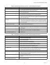
Table 6. Troubleshooting modulating economizer—outdoor enthalpy above setpoint.
Condition on Logic Module Should Be Condition Not Met
1. Red LED not lighted. 1. If the LED glows, the Logic Module recognizes conditions are good for free cool-
ing. Verify that conditions are above the enthalpy setpoint, see Note 2. Check wir-
ing to Enthalpy Control for a short from {SO} and {+}.
2. 24 Vac to terminals {TR} and {TR1}. 2. Check the wiring from [G] and [C] on the unit low voltage terminal strip. {TR} and
{TR1} power the actuator.
3. 24 Vac to terminals {1} and {TR1}. 3. Verify that there is a call for cooling from the thermostat. Without a call for cooling,
the compressor can not be in the normal air conditioning mode.
4. 24 Vac to terminals {2} and {TR1}. 4. If 24 Vac is not on {2} and {TR1}, the internal switch is not set correctly. Remove
the {SO} wire from the module. If 24 Vac is on {2} and {TR1}, the enthalpy control
is bad or the {SO} and {+} wires are shorted together. If no voltage to {2} and
{TR1}, the module is bad.
5. Continuity on terminals {1} and {2}, {3}
and {4}.
5. If there is not continuity for terminals {1} and {2}, the internal switch is not in the
correct position and the module is defective. If there is continuity from terminals
{1} and {2}, the red LED should not be lighted. If there is continuity on terminals
{3} and {4}, the internal switch is correctly energized. The damper actuator should
be in a min. position.
6. Compressor does not operate with all
above conditions correct.
6. Check the wiring from {2} to Y1 on the unit low voltage control board. If the LED is
not lighted, check 24 Vac from {2} to Y1.
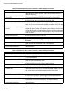
Second Stage
7. 24 Vac to terminals {3} and {TR1}. 7. Verify that you have a two-stage thermostat. Check for a call for a second stage
cooling. If 24 Vac is not on {3} and {TR1}, check wiring from Y2 on the thermostat
to the module.
8. 24 Vac to terminals {4} and {TR1}. 8. If {4} and {TR1} do not have 24 Vac, and {3} and {TR1} have 24 Vac, the internal
switch is not in the correct position. The module is defective.
9. Compressor does not operate with
second stage conditions met.
9. If all other functions are correct, check wiring from {4} to Y2 on the unit low voltage
terminal board.
Table 7. Troubleshooting modulating economizer—outdoor enthalpy below setpoint.
Condition on Logic Module Should Be Conditions Not Met
1. Red LED lighted. 1. Jumper terminals {SO} and {+}. If the LED lights, the module is okay, see Note 2.
Check wiring to enthalpy control.
2. 24 Vac to terminals {TR} and {TR1}. 2. Check the wiring from [G] and [C] on the unit low voltage terminal strip. {TR} and
{TR1} power the actuator.
3. 24 Vac to terminals {1} and {TR1}. 3. Verify there is a call for cooling from the thermostat. Without a call for cooling, the
motor can not be in the economizer mode.
4. No continuity on terminals {1} and {2}. 4. If there is continuity from terminals {1} and {2}, the red LED should not be lighted. If
there is continuity and the LED glows, the module is defective.
5. Continuity on terminals {3} and {5}. 5. If there is continuity on terminals {3} and {5}, the internal switch is correctly ener-
gized. Damper motor should be in a modulating mode.
6. Motor does not operate with all above
conditions met.
6. Jumper the mixed air sensor terminals {T} and {T1}. If the motor begins to operate,
check the wiring to the sensor. If correct, the temperature is below the sensor set-
point or it is defective. If the motor does not operate, and the wiring is correct and
the temperature is above the sensor setpoint, the motor is bad.
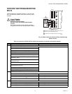
Second Stage
7. 24 Vac to terminals {3} and {TR1}. 7. Verify that you have a two-stage thermostat. Check for a call for a second stage
cooling. If 24 Vac is not on terminals {3} and {TR1}, check wiring from terminal Y2
on the thermostat to the module.
8. 24 Vac to terminals {5} and {TR1}. 8. If terminals {5} and {TR1} do not have 24 Vac, the internal switch is not in the cor-
rect position, assuming that terminals {3} and {TR1} have 24 Vac. The module is
defective.
9. Compressor does not operate with
second stage conditions met.
9. If all other functions are correct, check the wiring from terminal {5} to Y2 on the unit
low voltage terminal board.