


SOLID STATE ECONOMIZER SYSTEM
31 63-2484—2
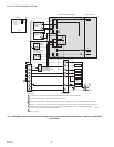
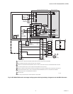
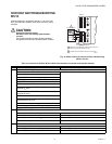
CHECKOUT AND TROUBLESHOOTING:
W7212
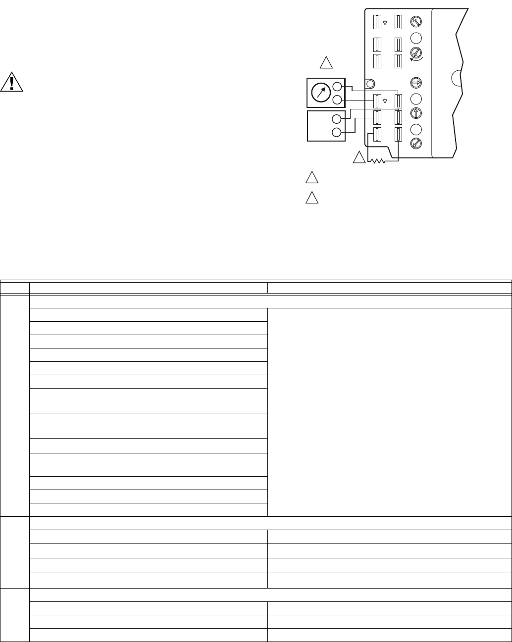
Checkout requires a 9V battery, 620 ohm, 1.2K ohm, 5.6K
ohm, and 6.8K ohm resistors. Use Table 10 and Fig. 36 for
checkout.
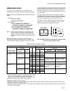
CAUTION
Equipment Damage Hazard.
Excessive force can damage potentiometer
controls.
Use a small screwdriver when adjusting enthalpy
changeover and minimum damper position controls.
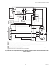
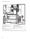
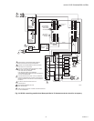
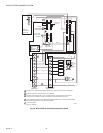
Fig. 36. Meter location for checkout and troubleshooting
(W7212 shown).
M20612
N1
P1
T1
N
2V
2V
2V
B
A
SR
SO
AQ
C
D
Free
Cool
10V
EXH
DCV
EXH
Set
10V
DCV
Max
10V
DCV
Set
Min
Pos
Open
P
T
AQ1
SO+
SR+
1
2
DC VOLTMETER
620 OHM RESISTOR
W7212
–
+
S
+
C7400
1
2
INSERT DC VOLTMETER BETWEEN AQ AND AQ1 FOR
CHECKOUT AND TROUBLESHOOTING.
JUMPER USED FOR SINGLE ENTHALPY CONTROL.
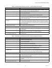
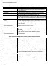
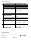
Table 10. Checkout for W7212, W7213, W7214 Economizers Connected to Honeywell Actuator.
Step Checkout Procedure Proper Response
1. CHECKOUT PREPARATION
Disconnect power at TR and TR1. All LED are off; Exhaust Fan contacts are open.
Disconnect devices at P and P1.
Jumper P to P1.
Place 5.6K ohm resistor across T and T1.
Jumper TR to 1.
W7212 only: Jumper TR to N.
If connected, remove C7400 Enthalpy Sensor from
terminals S
O
and +.
Connect 1.2K ohm 4074EJM Checkout Resistor across
terminals S
O
and +.
Put 620 ohm resistor across S
R
and +.
Set minimum position, DCV setpoint, and Exhaust
potentiometers fully CCW.
Turn DCV maximum position potentiometer fully CW.
Set enthalpy potentiometer to D.
Apply power (24 Vac) to terminals TR and TR1.
2. DIFFERENTIAL ENTHALPY
Execute step one, Checkout Preparation. –
Place 620 ohm resistor across S
O
and +. –
Place 1.2K ohm resistor across S
R
and +. Free cool LED turns on.
Remove 620 ohm resistor from S
O
and +. Free cool LED turns off.
3. SINGLE ENTHALPY
Execute step one, Checkout Preparation. –
Set enthalpy potentiometer to A (fully CCW). Free cool LED turns on.
Set enthalpy potentiometer to D (fully CW). Free cool LED turns off.