


SOLID STATE ECONOMIZER SYSTEM
63-2484—2 8
CAUTION
Personal Injury Hazard.
Spring-return assembly can release.
Leave end covers attached to the motor.
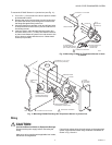
Location and Mounting
Locate motor as close as possible to the equipment to be
controlled. Refer to Fig. 4 for mounting dimensions.
1. Mount motor with the shaft horizontal to ensure maxi-
mum life.
NOTE: Operation in other positions is possible when required
by the application.
2. Remove crank arm (secured with two screws) from the
motor hub.
IMPORTANT
Position crank arm on hub so it does not strike motor
mounting surface during any portion of full stroke.
See Fig. 8.
3. Reposition the crank arm to accommodate specific
damper requirements.
NOTE: Crank arm position is adjustable in eight degree
increments.
4. Reconnect crank arm to the motor hub.
5. If there is an excess length of linkage rod, cut it to size.
Make necessary minor adjustments until desired opera-
tion is obtained.
6. Tighten all nuts and set screws.
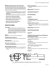
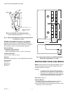
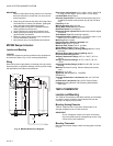
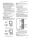
Fig. 8. Limits of crank arm rotation.
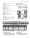
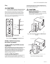
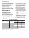
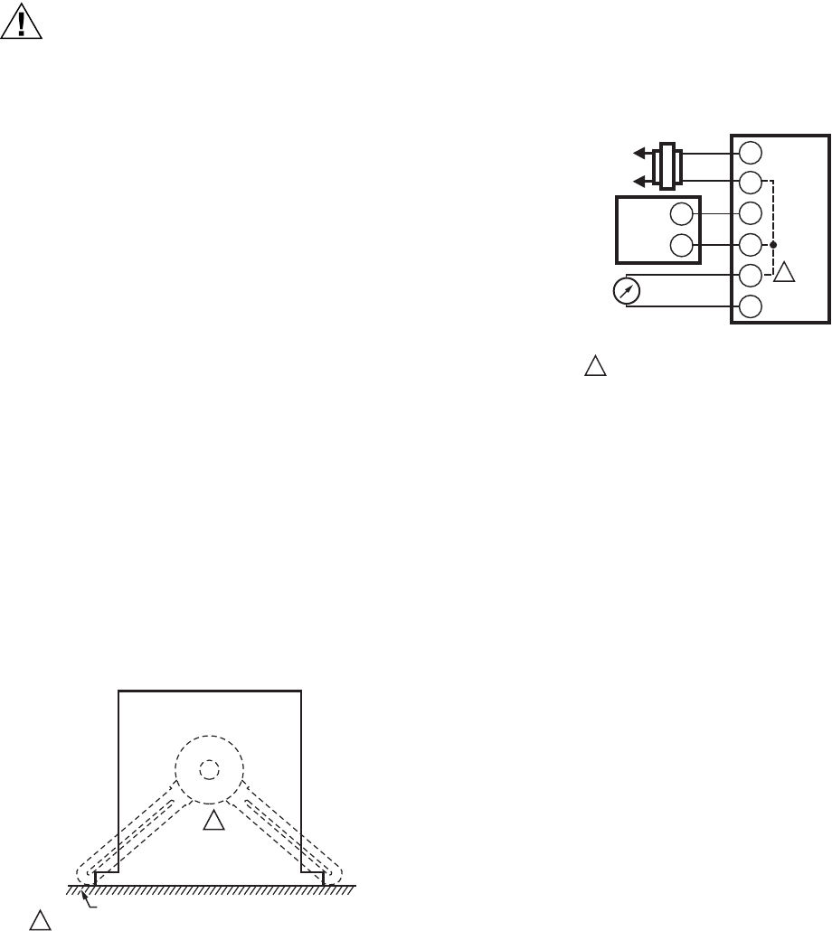
WIRING: M7215, M7415, M8405
All wiring must comply with applicable codes and ordinances.
Refer to Fig. 9 for typical hookup.
Fig. 9. Typical M7215 wiring.
C7046C Discharge Air Temperature Sensor
The sensor assembly consists of an aluminum sensor probe
(element housed internally) with attached flange that can be
mounted on a flat duct or plenum surface, or in a 2 in. by 4 in.
(51 by 102 mm) junction box, using two no. 8 screws.
Connections to the sensor are made through two 6 in. (152
mm) leadwires.
Location
Locate the sensor in the air duct or plenum where it can
sample average air temperature. Avoid locations where air
stratification can cause sensing errors.
Mounting
To mount the C7046C Sensor on a flat duct or plenum surface
(see Fig. 10):
1. Cut a 1/2 in. (13 mm) hole in the duct or plenum surface
at the desired location.
2. Insert the sensor probe into the duct or plenum hole until
the flange rests against the duct or plenum wall.
3. If necessary, use the flange as a template to mark and
drill two holes for no. 8 mounting screws.
4. Fasten the sensor to the duct or plenum surface with the
two no. 8 sheet metal screws (not provided).
1
1
CRANK ARM FIELD ADJUSTABLE IN 7.5 DEGREE INCREMENTS.
MOTOR MOUNTING SURFACE
M3850
MAXIMUM
OPEN
POSITION
MAXIMUM
CLOSED
POSITION
M17365
TR1
TR
M7215
2-10
VDC
CONTROL
METER INDICATING
MOTOR POSITION
(2-10 VDC)
L1
L2
IN+
OUT
–
IN–
+
–
OUT
+
DOTTED LINE REPRESENTS INTERNAL
CONNECTIONS OF THE M7215 ACTUATOR.
1
1