


SOLID STATE ECONOMIZER SYSTEM
63-2484—2 10
IMPORTANT
Failure to follow these wiring practices can introduce
electrical interference (noise) that can cause erratic
system operation:
a. Keep wiring at least one foot away from large induc-
tive loads such as motors, line starters, lighting bal-
lasts, and large power distribution panels.
b. Shielded cable is required in installations where
these guidelines cannot be met.
c. Ground shield only to grounded controller case.
d. Make good physical wiring connections to ensure
good electrical connections.
e. Make sure that building earth ground connections
are not intermittent or missing.
f. Mount sensor only in recommended environment.
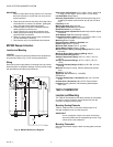
MS7505 Damper Actuators
Location and Mounting
LOCATION
Locate the actuator as close as possible to the equipment to
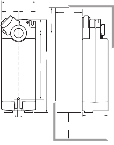
be controlled. Refer to Fig. 12 for mounting dimensions.
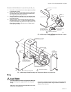
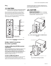
Wiring
Disconnect power supply before connecting wiring to prevent
electrical shock or equipment damage. All wiring must comply
with applicable local codes and ordinances.
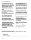
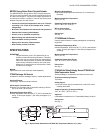
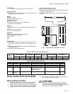
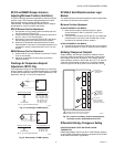
Fig. 12. MS7505 Dimensions Diagram.
Dimensions, Approximate 9.72 in. high x 3.94 in. wide x 2.95
in. deep (247 mm high x 100 mm wide x 75 mm deep)
Fail Safe Mode Spring Return
Electrical Connections Enclosed screw terminal strip (22 to
14 AWG) (Enclosed screw terminal strip [0.324 to 2.08 sq
mm])
Frequency 60 Hz
Manual operation Manual Crank
Spring Return Direction By orientation
Rotational Stroke 95 ±3 degrees
Rotational Stroke Adjustment Mechanically limited 5 degree
increments
Shaft Adapter Type Self-centering clamping
Compatible Damper Shafts 3/8 to 1.06 round or 3/8 to 11/16
square (10 to 27 round or 10 to 18 square)
Mounting Direct Coupled
External Auxiliary Switches Available Yes
Rated Torque (44 lb-in. (5 Nm)
Maximum Stall Torque 75 lb-in. (8.5 Nm)
Spring Return Torque 44 lb-in. (5 Nm)
Maximum Noise Rating, Holding (dBA @ 1m) 20 (no audi-
ble noise)
Maximum Noise Rating, Driving (dBA @ 1m) 40
Environmental Rating NEMA2
Ambient Temperature Range -40°F to +140°F (-40°C to
+60°C)
Storage Temperature Range -40°F to +158°F (-40°C to
+70°C)
Operating Humidity Range (% RH) 5 to 95% RH, non-con-
densing
Materials Aluminum housing, Plenum rated plastic access
cover
Weight 6 lb (2.72 kg)
Approvals:
CE: 89/336/ECC, 73/23/EEC
C-Tick N314
Canadian Underwriters Laboratories, Inc. cUL C22.2 No.
24-93
Underwriters Laboratories, Inc. UL873, Plenum Rated
Includes Mounting Bracket, Self-Centering Shaft Adapter,
3mm crank
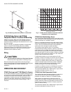
T6031H THERMOSTAT
Location and Mounting
The T6031H Thermostat mounts either vertically or horizontally
on a wall or panel. Locate the remote bulb as far from the
controller as capillary tubing allows.
Mounting Sensing Elements
T6031H: Install the bulb in the return airflow where air of
average temperature can circulate around it.
IMPORTANT
Do not overtighten clamps to the point of distorting
the sensor bulb because overtightening causes a sig-
nificant shift in bulb calibration.
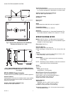
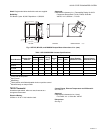
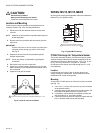
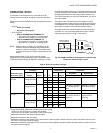
Mounting Thermostat
Mount the thermostat using the back mounting plate as shown
in Fig. 5.
9-3/4
(247)
1-9/16
(40)
2-1/2
(64)
MIN.
3 (76)
MIN.
3 (76)
MIN.
FROM
SHAFT
END
6-1/8
(156)
1-9/16
(40)
1-9/16
(40)
3-15/16 (100)
2-15/16 (75)
1/4 (6)
M20952