


SOLID STATE ECONOMIZER SYSTEM
11 63-2484—2
Wiring
CAUTION
Can Cause Electrical Shock or Equipment Damage.
Disconnect power supply before connecting wiring.
Disconnect the power supply before connecting wiring to
prevent electrical shock and equipment damage. All wiring
must comply with applicable local codes and ordinances.
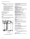
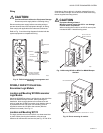
Refer to Fig. 13 and the wiring diagrams furnished with the
system equipment to complete the wiring.
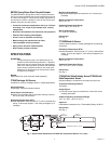
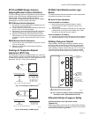
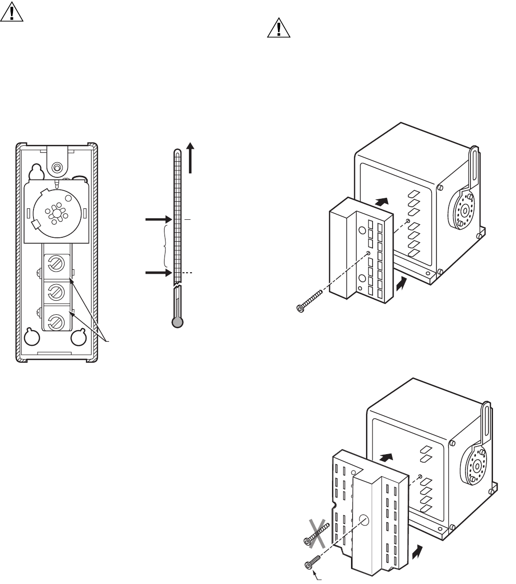
Fig. 13. T6031H switch terminal arrangement and
switching.
W7459A,C AND W7212 Solid State
Economizer Logic Module
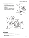
Location and Mounting W7459 Economizer
Logic Module
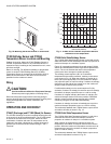
Mount the W7459 Economizer Logic Module on the side of the
M7415 or M8405 Damper Actuator. When planning the
installation, allow enough clearance for maintenance and
service. Install the W7459 Economizer Logic Module where it
is protected from rain and snow. One mounting screw is
supplied to secure the W7459 to the actuator (after the
actuator is mounted). See Fig. 14.
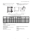
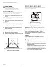
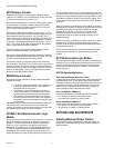
Location and Mounting W7212
The logic modules mount on an M7215 or a sheet metal duct
or panel. When planning the installation, allow enough
clearance for maintenance and service (see Fig. 15 and 16 for
dimensions). Mount device in a location protected from rain,
snow and direct sunlight. Secure device to sheet metal using
the two supplied mounting screws.
CAUTION
Equipment Damage Hazard.
Mounting screws longer than 5/8 in. can damage
internal motor components.
When mounting the module to an M7215 use only the
included #6 5/8 in. thread-forming screw.
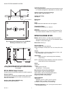
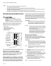
Fig. 14. Mounting W7459 on M7415 or M8405 Damper
Actuator.
Fig. 15. Direct mounting of module.
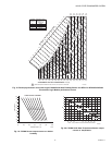
SETPOINT
FOR T6031H
SETPOINT
SWITCH
DIFFERENTIAL
TEMPERATURE
RISE
R AND W LOCATIONS
DEPEND ON MODEL
AND CONSTRUCTION
W
B
R
BREAKS R-B;
MAKES R-W
ON RISE
MAKES R-B;
BREAKS R-W
ON FALL
M9089
M9091
W7459
ECONOMIZER PACKAGE
M7415, M7405 OR
M8405 ACTUATOR
M20717B
5/8 INCH SCREW INCLUDED WITH LOGIC MODULE.
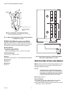
M7215 DAMPER MOTOR
ECONOMIZER
LOGIC MODULE