


SOLID STATE ECONOMIZER SYSTEM
15 63-2484—2
M7415 and M8405 Damper Actuators
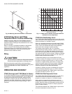
Adjusting Minimum Position (Ventilation)
The M7415 Damper Actuator is adjusted for desired minimum
position using a Q709 Actuator Mounted Minimum Position
Potentiometer and/or a remote S963B1136 Manual
Potentiometer. The M8405 Damper Actuator has an integral
thumbwheel for minimum position adjustment.
M7415 Minimum Position Adjustment
1. Run actuator to fully closed position and disconnect 24
Vac from terminals TR and TR1.
2. Connect minimum position potentiometer to terminals P
and P1 (T and T1 are disconnected).
3. Reconnect 24 Vac to terminals TR and TR1 and adjust
the potentiometer for the desired minimum position.
4. When the Q709 Actuator Mounted Minimum Position
Potentiometer is used and a remote potentiometer is not
connected in series, jumper terminals P and P1 on the
Q709A.
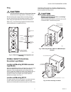
M8405 Minimum Position Adjustment
1. Connect the 24 Vac to the actuator at terminals T and X
(D is not connected).
2. Adjust the thumbwheel on the actuator for desired
minimum position.
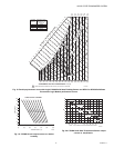
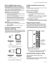
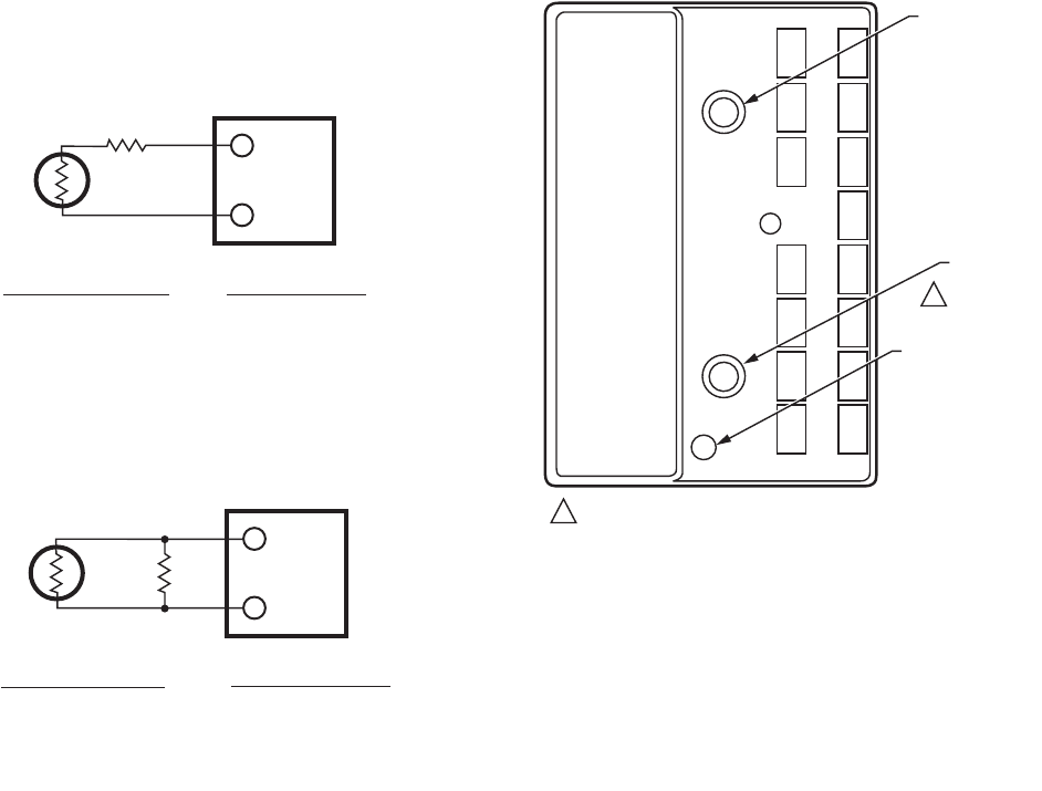
Discharge Air Temperature Setpoint
Adjustment—M7415 Only
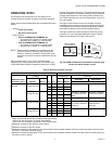
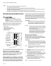
This temperature range can be adjusted either up or down by
wiring a resistor in series (to increase the setpoint) or in parallel
(to decrease the setpoint) with the C7150B, depending on the
application. See Fig. 21 and 22 for explanation.
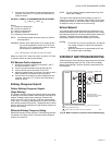
Fig. 21. Increasing C7150B setpoint.
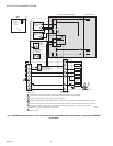
Fig. 22. Decreasing C7150B setpoint.
W7459A,C Solid State Economizer Logic
Module
Two potentiometers with small screwdriver slots for adjustment
are located on the face of the module.
Minimum Position Adjustment
W7459A ECONOMIZER LOGIC MODULE
1. Make sure the factory-installed jumper is in place
across terminals P and P1 (terminals T and T1 are
disconnected.
2. Connect 24 Vac at terminals TR and TR1 and adjust the
potentiometer on the face of the W7459A with a small
screwdriver for desired minimum position.
W7459C ECONOMIZER LOGIC MODULE
1.
Connect 24 Vac at terminals TR and X (D is not connected).
2.
Adjust thumbwheel on motor for desired minimum position.
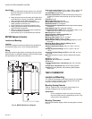
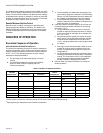
Enthalpy Changeover Setpoint
Single enthalpy: the enthalpy changeover setpoint is set to
return the outdoor air damper to the minimum position when
the enthalpy rises above its setpoint. The enthalpy setpoint
scale markings, located on the W7459, are A, B, C, D; see Fig.
18 for the corresponding control point. The factory-installed
620-ohm jumper must be in place across terminals + and S
R
.
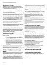
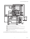
Fig. 23. Location of enthalpy setpoint potentiometer,
minimum position potentiometer and LED.
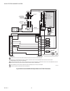
Differential Enthalpy Changeover Setting
(USE THIS OPTION ONLY WITH TWO-STAGE COOLING
THERMOSTATS.)
Differential enthalpy control uses two C7400 Enthalpy Sensors
or two C7650A Temperature Sensors connected to one W7459
Solid State Economizer Logic Module.
T
USE 1%, 1/8 W OR HIGHER RESISTOR
M1544C
T1
M7415
C7150
R
RESISTOR VALUE (OHMS)
681
2760
3650
4420
4750
4870
NO RESISTOR
C7150B SETPOINT °F (°C)
54.5—61.5 (12.5—16.4)
68.4—80.1 (20.3—26.8)
87.4—110.3 (30.8—45.5)
104.7—150 (40.4—65.5)
116—194 (46.7—90)
120—300 (49—149)
50—56 (10—13.3)
T
USE 1%, 1/8 W OR HIGHER RESISTOR
M1545C
T1
M7415
C7150
R
RESISTOR VALUE (OHMS)
18.2K
24K
30K
NO RESISTOR
C7150B SETPOINT °F (°C)
36—44 (2.2—6.7)
39.5—47 (4.0—8.3)
42—49 (5.6—9.4)
50—56 (10—13.3)
1
1
M9098B
ENTHALPY
CHANGEOVER
SETPOINT
MINIMUM
DAMPER
POSITION
SETTING
LED LIGHTS
WHEN OUTDOOR
AIR IS SUITABLE
FOR FREE COOLING
MINIMUM DAMPER POSITION ADJUSTMENT
IS PRESENT ONLY ON W7459A,D MODELS.