SOLID STATE ECONOMIZER SYSTEM
17 63-2484—2
OPERATION: W7212
The purpose of the economizer is to use outdoor air for
cooling, whenever possible, to reduce compressor operation.
Power at the N terminal determines the Occupied/Unoccupied
setting:
— W7212:
• 24 Vac (Occupied).
• No power (Unoccupied).
— W7213,W7214:
• W7213 (CHANGEOVER TERMINAL B)
— 24V power to B: System is in heating mode.
— No power to B: System is in cooling mode.
• W7214 (CHANGEOVER TERMINAL O)
— 24V power to O: System is in cooling mode.
— No power to O: System is in heating mode.
NOTE: When module is operating in Occupied mode, the
minimum position is defined by the potentiometer.
When the module is operating in Unoccupied mode,
and there is no call for cooling, the damper drives fully
closed.
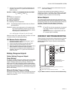
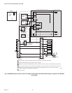
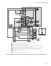
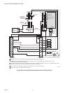
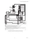
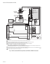
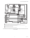
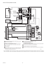
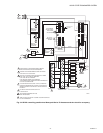
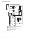
When wired as shown in Fig. 28–33, the logic module
responds to the cooling thermostat signal. The system uses
C7400 Solid State Enthalpy Changeover Sensor(s) or C7650
Dry Bulb Temperature Sensor(s). The C7400 responds to both
dry bulb temperature and humidity, allowing use of outdoor air
at higher temperatures for free cooling when humidity is low.
The C7650 responds only to dry bulb temperature; use only in
dry, arid climates.
The logic module functions as a true first stage of cooling
providing maximum energy economy during the cooling cycle.
It automatically locks out free cooling during heating; holding
the outdoor air damper at the minimum position setting.
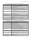
The logic module can operate as either a basic free cooling
controller, or it can incorporate additional functions. Table 5
details the input/output (I/O) logic of the module.
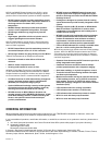
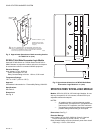
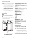
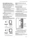
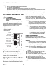
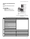
Fig. 24. S963B1128 Remote Potentiometer used with logic
module for remote damper control.
a
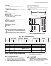
For single enthalpy control, the module compares outdoor enthalpy to the ABCD setpoint.
b
Power at N terminal determines Occupied/Unoccupied setting:
• W7212: 24 Vac (Occupied), no power (Unoccupied).
• W7213,W7214: No power (Occupied), 24 Vac (Unoccupied).
c
Modulation is based on the mixed air sensor signal.
d
Modulation is based on the DCV signal.
e
Modulation is based on the greater of DCV and mixed air sensor signals, between minimum position and either maximum posi-
tion (DCV) or fully open (mixed air signal).
f
Modulation is based on the greater of DCV and mixed air sensor signals, between closed and either maximum position (DCV) or
fully open (mixed air signal).
M20603A
P1
P
ECONOMIZER
R
MINIMUM
POSITION
ADJUSTMENT
W
B
CW
CLOSE
S963B1128 REMOTE
POTENTIOMETER
CW
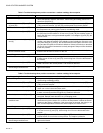
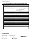
Table 5. W7212 Economizer I/O Logic.
INPUTS OUTPUTS
Demand Control
Ventilation (DCV)
Enthalpy
a
Y1 Y2
Compressor N Terminal
b
Outdoor Return Stage 1 Stage 2
Occupied
b
Unoccupied
b
Damper
Below set (DCV
LED Off)
High (Free
Cooling LED Off)
Low On On On On Minimum position Closed
On Off On Off
Off Off Off Off
Low (Free
Cooling LED On)
High On On On Off
Modulating
c
(between
min. position and full-
open)
Modulating
c
(between
closed and full-open)
On Off Off Off
Off Off Off Off Minimum position Closed
Above set (DCV
LED On)
High (Free
Cooling LED Off)
Low OnOnOn On
Modulating
d
(between
min. position and DCV
maximum)
Modulating
d
(between
closed and DCV
maximum)
On Off On Off
Off Off Off Off
Low (Free
Cooling LED On)
High On On On Off
Modulating
e
Modulating
f
On Off Off Off
Off Off Off Off