


Installation
32 Apollo SL30 Installation Manual
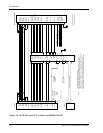
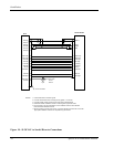
+GS Flag
-GS Flag
GSI Down
GSI Up
Glideslope Flag +
30
31
28
32
13
14
Right Dev +
Glideslope Flag -
Glideslope +Up
Glideslope +Down
Century
NSD 360A
Century
NSD 1000
29
30
28
17
18
27
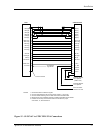
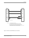
SL30
CD 132
Left Dev +
NAV Flag +
NAV Flag -
From +
To +
OBS Rotor H
OBS Rotor C
OBS Stator D
OBS Stator E
OBS Stator F
OBS Stator G
32
31
33
34
16
15
23
24
25
26
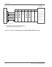
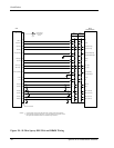
NAV Flag +
NAV Flag -
+ From
+ To
Rslvr{C}
Rslvr{D}
Rslvr{E}
CDI Left
CDI Right
Rslvr{F}
Rslvr{G}
Rslvr{H}
29
10
25
24
26
7
34
16
12
11
15
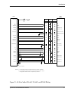
Back Course
Lamp Voltage
From Dimmer
Circuit
Amber
BC
Light
37-Pin Connector
29
30
28
17
18
27
32
31
33
34
16
15
23
24
25
26
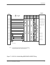
CD 132
Century Flight
Systems
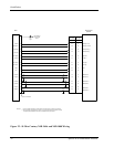
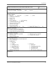
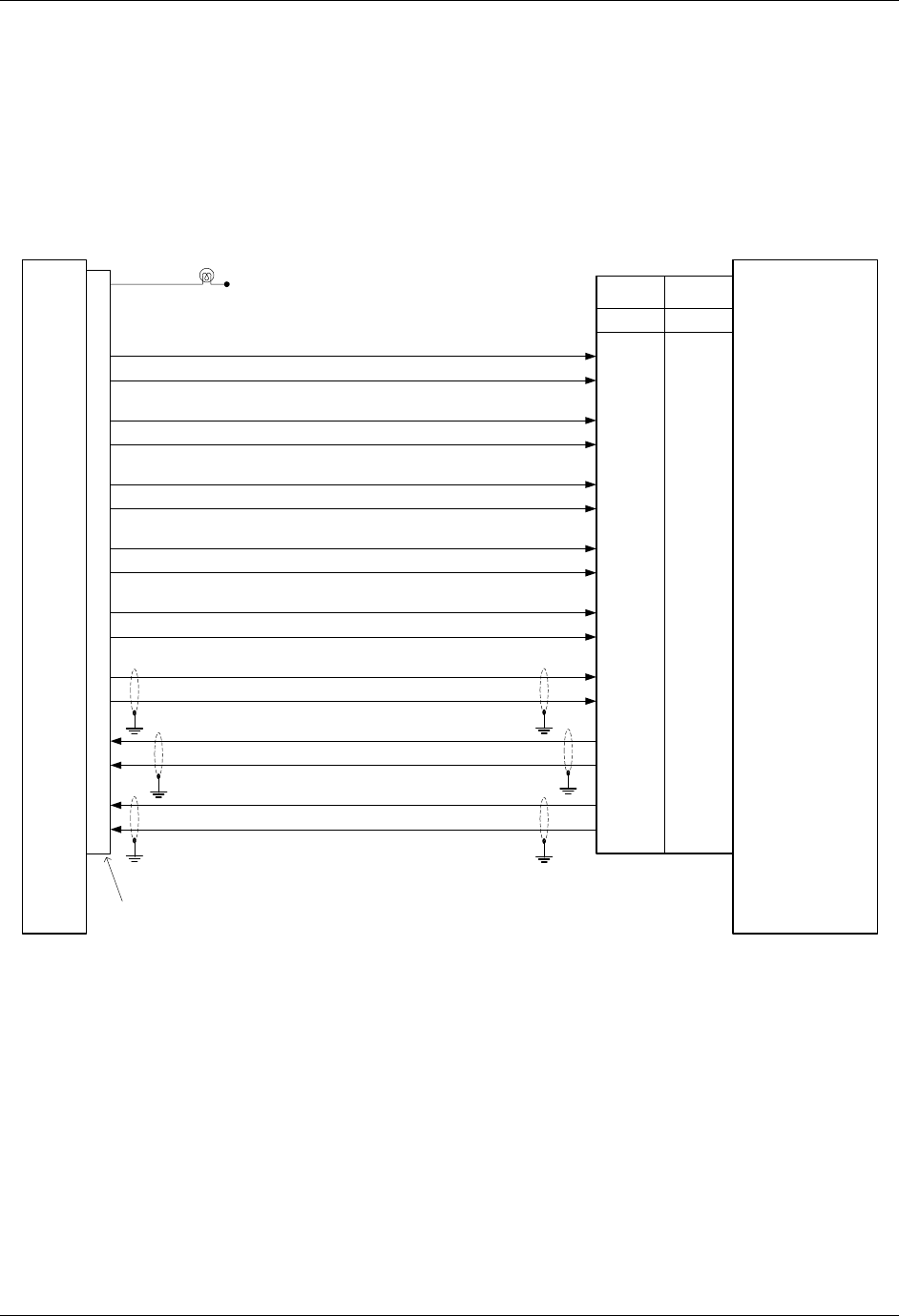
NOTES:
1. Connect shield grounds to aircraft chassis with as short a conductor as practical.
2. Not all indicator connections are shown, only those interfacing to the SL30. Consult
the appropriate installation manuals for complete wiring instructions.
Figure 22 - SL30 to Century NSD 360A and NSD 1000 Wiring