


Installation
Apollo SL30 Installation Manual
25
Rslvr{C}
Rslvr{D}
Rslvr{E}
24
7
26
25
1
2
3
6
5
4
Rslvr{H}
Rslvr{C}
Rslvr{D}
Rslvr{E}
Rslvr{F}
Rslvr{G}
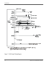
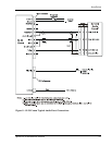
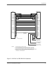
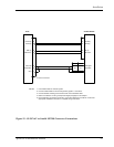
STEC IND-351A
+NAV Flag
-NAV Flag
+GS Flag
+TO Flag
+FR Flag
CDI Left
CDI Right
GSI Down
GSI Up
+NAV Flag
-NAV Flag
+GS Flag
-GS Flag
+TO Flag
+FR Flag
CDI Left
CDI Right
GSI Down
GSI Up
10
29
28
12
11
14
13
30
31 14
13
12
11
10
9
16
15
8
7
Back Crse
ILS Enbl
15
33
BC Ann.
Ann. Dim
27.5 Dim
13.8 Dim
22
23
25
24
Ground21
To Auto-Pilot
High Sense
BC Annunciator
Dimmer 12V max
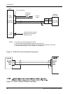
Backlight Dimmer
14 V Systems
Backlight Dimmer
28 V Systems
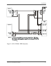
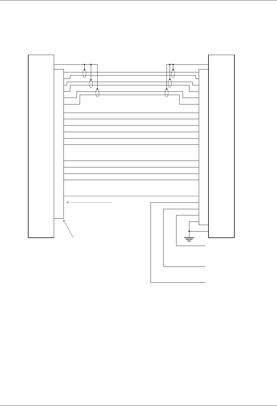
NOTES: 1. Use shieled cable for Resolver signals
2. Connect cable shields to the mounting frame: pigtails < 1.25 inches
3. Connect shields chassis ground at both ends of each shielded cable
4. Reference the ACU installation manual if installing NAV/GPS source selector.
5. Installer should verify that the STEC IND-351A contains the proper
annunciator, i.e., BC backcourse.
Rslvr{F}
Rslvr{G}
Rslvr{H}
16
34
(GND if 14V)
32-GS Flag
SL30
37-Pin Connector
Figure 15 - SL30 NAV to STEC IND-351A Connections