


Installation
16 Apollo SL30 Installation Manual
USE OF SPLITTER AND COMBINER
The SL30 is the smallest, most advanced NAV/Comm unit on the market. Its size dictates
room for only one Comm antenna input and one NAV antenna input. It incorporates an
internal diplexor circuit. This means that the input VHF signal must not strip the glideslope
(330 MHz) signal from the NAV (108 MHz) signal. Do not install an external diplexor.
It is recommended that a single VOR/Localizer/Glideslope antenna be used for the
installation. Most VOR/LOC-only antennas will still provide an adequate glideslope signal
for the Apollo SL30 to operate normally. In rare cases, it may be necessary to combine
antenna signals. When the signals are combined, the systems overall performance may be
slightly degraded, but the glideslope signal may increase to an acceptable level.
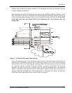
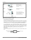
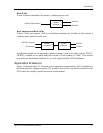
Dual Antennas
If separate VOR and glideslope antennas are used on the aircraft, a splitter/combiner must be
used.
SL30 NAV Input
Splitter/
Combiner
VOR/LOC Antenna
GS Antenna
1
2
S
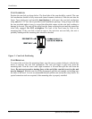
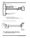
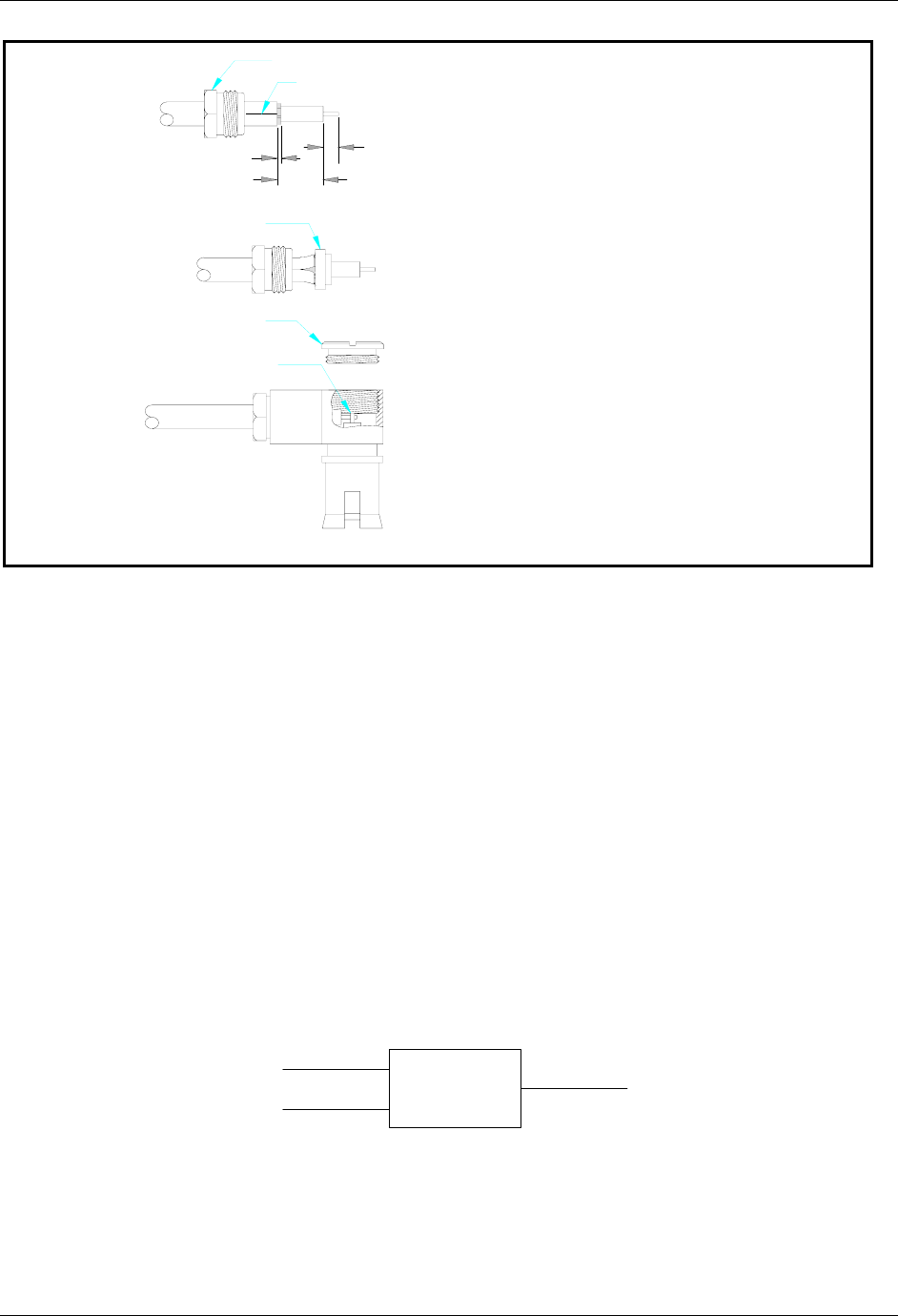
Slit 1/4" (2X)
Clamp Nut
0.375
0.031
- Slide clamp nut over coax.
- Strip coax as illustrated.
- Cut two 1/4" slits in jacket 180
degrees apart.
Braid Clamp
Cap
Solder Center
Conductor
Step 1.
Step 2.
Step 3.
- Slide braid clamp over end of coax and
under the braid.
- Insert coax with braid clamp into
connector and tighten clamp nut securely.
- Solder the center conductor of the coax
to the contact as illustrated.
- Attach the cap and secure tightly.
Assembly instructions for right angle connector part #162-1008
0.125
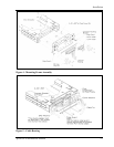
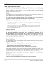
Figure 6 - Rear Coax Connector Assembly