


Installation
Apollo SL30 Installation Manual
9
SECTION 2 - INSTALLATION
This section describes the installation of the SL30 including mounting, wiring, and
connections. A post installation check-out procedure is included at the end of this section.
PRE-INSTALLATION INFORMATION
Always follow good avionics installation practices per FAA Advisory Circulars (AC) 43.13-
1B, 43.13-2A, and AC 20-67B, or later FAA approved revisions of these documents.
Follow the installation procedure in this section as it is presented for a successful installation.
Read the entire section before beginning the procedure. Perform the post installation check-
out before closing the work area in case problems occur.
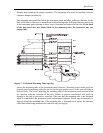
INSTALLATION OVERVIEW
A successful installation should start with careful planning including determination of
mounting location for the SL30, antenna mounting, connections to microphones, speakers,
and headphones, cable routing, and other required modifications. Once the mounting location
has been determined, prepare the mounting frame for installation. It may be easier to complete
the wiring harness and attach the connectors to the mounting frame before installing the
mounting frame.
INSTALLATION CONSIDERATIONS
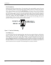
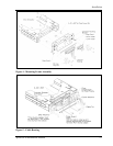
MOUNTING CONSIDERATIONS
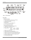
The SL30 is designed to mount in the avionics stack in the aircraft instrument panel within
easy view and reach of the pilot. The standard package includes a mounting frame for ease of
mounting, connections, and service of the unit. Allow an additional one-inch clearance to the
rear of the mounting frame for connectors and cables.
For typical installations, the SL30 does not require external cooling. When mounting the unit,
leave a clearance of 1/8 to 1/4 inch between avionics to allow for air circulation.
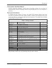
MINIMUM SYSTEM CONFIGURATION
VFR Installation
VFR installation need only include an SL30 with power, audio, and antenna connections.
Without an external CDI, no glideslope information is obtainable. However, the unit will
maintain full VOR and Localizer functionality including an internal CDI display.
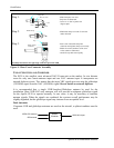
IFR VOR/LOC Installation
IFR installation requires:
• SL30
• External CDI/HSI indicator that meets the following criteria:
1. The course deviation indicator shall have an input impedance of 1 k ohm ± 10% and a
deflection sensitivity of 150 mV ± 10% for full scale deflection.
2. The valid flag shall have an input impedance of 1 k ohms ± 10%.