


Installation
Apollo SL30 Installation Manual
11
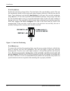
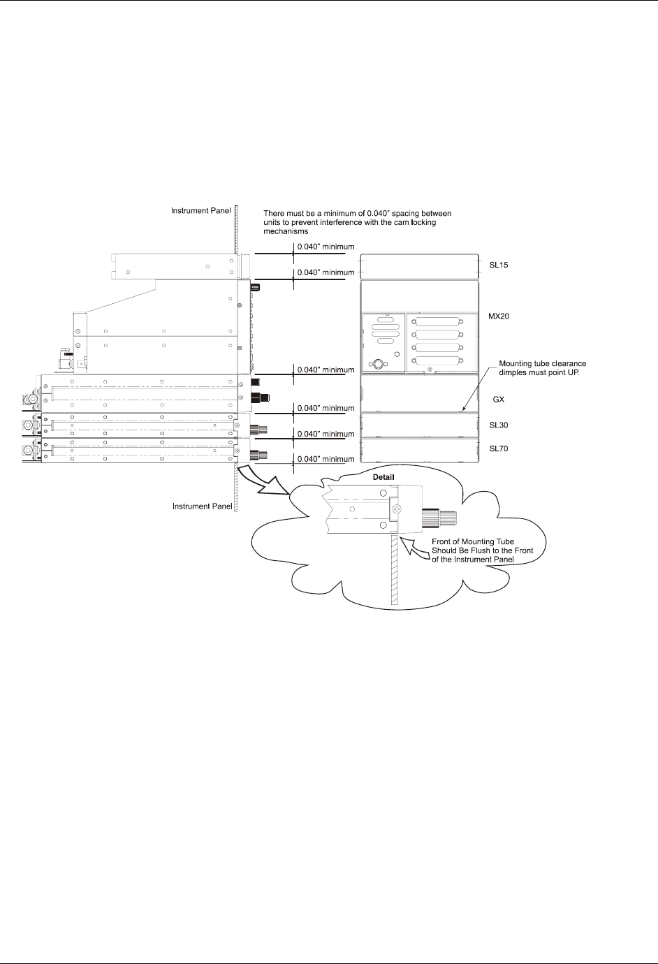
dimples help maintain the proper clearance. The mounting tube must be installed with the
clearance dimples pointing up.
The mounting tube should be flush to the instrument panel and allow sufficient clearance for the
back of the bezel of the unit to mount flush to the mounting tube. Sufficient clearance must exist
in the instrument panel opening to allow ease of insertion and removal of the unit. If the back
of the unit bezel does not mount flush to the mounting tube, the connector may not
engage fully.
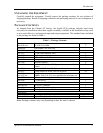
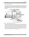
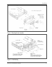
Figure 2 - Full Stack Mounting Tube Spacing
Secure the mounting tube to the instrument panel structure. Mounting screw heads must not
protrude into the mounting tube. Be sure to use the appropriate screws so the unit will slide in
and out freely. The screws attaching the mounting tube to the instrument panel structure must
not interfere with the insertion of the unit. Failure to prevent interference will result in
damage to the unit or prevent its insertion. Take care that the mounting tube is not distorted
when it is attached to the instrument panel and structural supports. Shims may be necessary to
properly install the mounting tube. If the mounting tube is distorted out of square, the unit may
either bind when being inserted or the cam lock may not engage.