


Installation
Apollo SL30 Installation Manual
15
MICROPHONE INPUTS
Microphone input connections should be made using a twisted pair shielded cable. Attach the
signal ground to the mic ground pin on the rear connector and connect the shield to the rear
connector plate.
TRANSMIT KEY INPUT
The TxKey input on the rear connector must be pulled low to ground to enable the
transmitter. This input should be connected to a microphone or yoke mounted momentary
push button switch.
INTERCOM SELECTOR SWITCH
The SL30 includes a voice activated intercom function that can be enabled by an external
control switch. This is an optional connection.
When making connection for the intercom selection, connect the intercom selection input to a
remote mounted normally open switch (an alternate action switch can be used). Connect the
other terminal of the switch to ground. The intercom function is enabled when the input is
pulled low to ground.
REMOTE FLIP/FLOP INPUT
The SL30 includes a remote flip/flop input. This is an optional input that can be connected to
a remote mounted (such as on the yoke) momentary push button switch which pulls the input
low to ground. The remote flip/flop input will only toggle the Comm frequencies when Comm
frequencies are displayed and will only toggle NAV frequencies when NAV frequencies are
displayed.
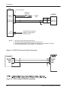
ANTENNA INSTALLATION AND CONNECTIONS
COMM AND NAV ANTENNAS
The SL30 requires a standard 50Ω vertically polarized Comm antenna and a horizontally
polarized NAV/VOR/Localizer/Glideslope antenna. Follow the antenna manufacturer’s
installation instructions for mounting the antennas. The Comm antenna should be a standard
Comm antenna that operates on Comm frequencies between 118.00 and 137.000 MHz. The
NAV antenna should be a VOR/Localizer/Glideslope NAV antenna that receives VOR
frequencies between 108 and 117.95 MHz, and localizer frequencies between 108 and 112
MHz and glideslope information between 328.6 and 335.4 MHz.
The NAV and Comm antennas should also be mounted as far apart as practical from the ELT
antenna, preferably one on top and the other on the bottom of the aircraft fuselage. Some
ELTs have exhibited re-radiation problems generating harmonics that may interfere with GPS
signals. This can happen when the Comm (SL40 or any other Comm) is transmitting on
certain frequencies such as 121.15 or 121.175 MHz, which may cause the ELT output circuit
to oscillate from the signal coming in on the ELT antenna coax.
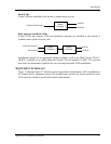
The antenna coax cable should be made of RG-142B or a comparable quality 50Ω coax.
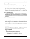
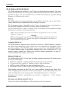
Assembly instructions for the rear coax connector are included in Figure 6.