


Installation
14 Apollo SL30 Installation Manual
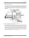
ELECTRICAL CONNECTIONS
The SL30 installation kit includes 15- and 37-pin d-sub shells and crimp contacts. The crimp
contacts are specified for 20 to 24 awg wire. Make the crimp connections with a crimp tool as
specified on page 6. All wires should be 20 to 24 AWG unless otherwise specified. Wiring
diagrams are included in this section.
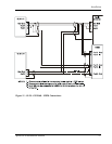
POWER
The SL30 requires two power connections, one for the Nav side of the unit, the other for the
Comm. Make the power connections to the unit using 20 awg wire.
The Comm power input is internally fused at 7 amps. A separate 5 amp circuit breaker or
fuse should be installed for downline overload or short circuit protection.
The NAV internal fuse is 3 amps. A separate 2 amp circuit breaker or fuse should be installed
for downline overload or short circuit protection.
Note: Circuits should be protected in accordance with guidelines in AC 43.13-1B,
chapter 11, section 4.
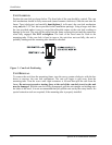
Warning
When connecting power to the unit, reversing the polarity of the connection will
blow the internal fuse. The internal fuse requires replacement at the factory or
factory authorized repair center.
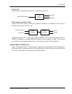
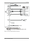
AVIONICS OUTPUTS
The SL30 includes a complete avionics interface for resolvers, CDI/HSI indicators, autopilot,
and back course annunciator. These outputs are to be connected as appropriate for the
particular installation. The CDI/HSI outputs may be connected to a dedicated CDI or HSI or
to a shared indicator using an appropriate switching relay, such as an Apollo ACU. The
avionics outputs available are listed in the Avionics Outputs specification on page 42.
Connect the annunciator outputs as necessary.
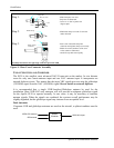
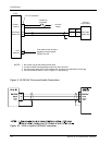
SERIAL INTERFACE
The SL30 includes an RS-232 serial port for making optional connections. The serial port can
be used for connecting to:
• Resolvers, indicators, or electronic flight instruments that accept serial data
• GX series units for Comm/NAV frequency transfers from the database
• MX20 to display VOR data on a map and database interface
• RMI/DME control box allows DME tuning, DME display, and OBI output
When making connections to the SL30, use a three conductor shielded cable. Make RxD,
TxD, and signal ground connections to the 37-pin connector. Connect the shield(s) to the rear
of the mounting frame on the connector plate. The shield leads must be < 1.25 inches.
Complete serial interface specifications are included in Appendix E – Serial Interface
Specifications.
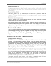
SPEAKER AND HEADPHONE OUTPUTS
Connect the speaker and headphones to the output pins on the rear connector.