


For maximum battery performance, be sure to drain your Ni-Cad pack as
completely as possible before recharging in order to ensure longer life. If your
battery pack seems to have no capacity even after being charged, completely
discharge it by leaving the power on overnight. Then fully charge the battery
pack again. If the battery pack still does not retain a charge, it will be necessary
to purchase a new battery pack. There is no hazard associated with powering
up your GPSMAP 175 and charging the battery pack at the same time.
DC W
iring
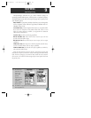
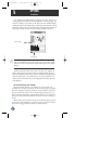
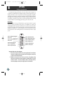
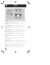
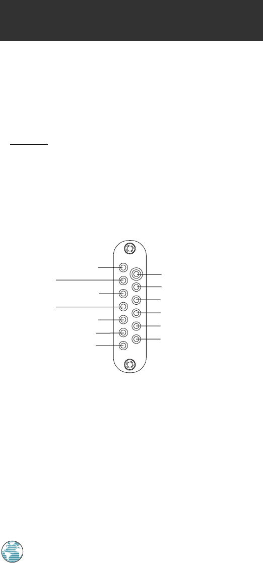
The GPSMAP 175 may be hard-wired to your boat’s 6-40v DC system
using an optional power/data cable (part no. 320-00054-00). Consult the
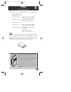
wiring diagram below for proper connections. The connector end of the cable
attaches to the back of the unit using either the long brass thumb screws
supplied or standard M3 x .5 (6mm) machine screws. The connector end may
also be attached to the mounting bracket for convenient attachment to ship’s
power
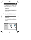
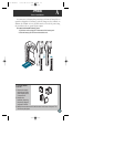
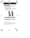
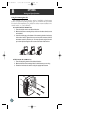
To attach the unit to the adapter:
1. Place the connector end over the contact pad located on the bottom
of the unit, making sure the connector end is facing the correct way
in order to match the terminals.
2. Match the two small screw holes, and secure the adapter using
either the long thumb screws supplied or standard M3 x .5 (6mm)
machine screws. To use this adapter with the mounting bracket,
insert the adapter connector through the slot in the bracket.
APPENDIX
Wiring & Specifications
76
B
PIN 1 (Black):Negative
PIN 3 NC
PIN 5 (Brown):Data In
PIN 7 NC
PIN 9 (Orange):NC
PIN 11 (Pink):NC
PIN 13 (Green):NC
PIN 2 (Red):Positive
PIN 4 (Blue):Data Out
PIN 6 (Yellow):Alarm
PIN 8 (White):NC
PIN 10 (Purple):NC
PIN 12 (Gray):NC
175 Manual 7/31/98 3:58 PM Page 76