


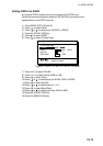
INTERFACE UNIT IF-2500
10-17
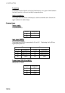
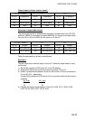
Output signal (contact closure signal)
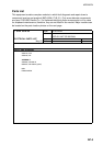
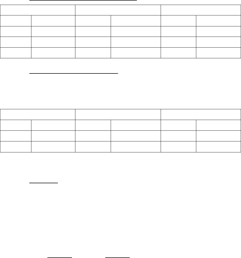
J10 (WPT alarm) J11 J12
Pin no. Designation Pin no. Designation Pin no. Designation
#1 Alarm signal #1 Alarm signal #1 Alarm signal
#2 Alarm signal #2 Alarm signal #2 Alarm signal
#3 GND #3 GND #3 GND
Selection of output data format
The output data format is selectable by changing a jumper block; A for RS-422
and B for NMEA. For example, to select NMEA for J4, change the jumper block
from A to B on J401 and J402. Do the same on J5 thru J9.
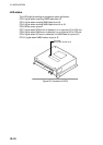
J10 (WPT alarm) J11 J12
Pin no. Jumper Pin no. Jumper Pin no. Jumper
J4 J401/J402 (A) J5 J501/J502 (A) J6 J601/J602 (A)
J7 J701/J702 (A) J8 J801/J802 (A) J9 J901/J902 (B)
Default jumper setting is shown in parenthesis.
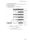
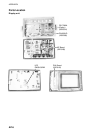
Self test 2
The test requires an external loop to check I/O. Follow the steps below to carry
out the test.
1) Set the #4 segment of DIP switch S1 to the ON position.
2) Temporarily disconnect input and output connectors J2 and J4.
3) Solder a jumper block between J2 and J4; #3 and #4 of J2 are connected to
#1 and #2 of J4, respectively.
Jumper block consists of XH-6 pin and 4 pin connectors with two short wires
as below.
XH, 6 pin
XH, 4 pin
#3 - - - #1
#4 - - - #2
4) Change the jumper block between J2 and J5; J2/J6, J2/J7, J2/J8, J2/J9,
J3/J4, J3/J5, J3/J6, J2/J7, J2/J8, J2/J9.