


xi
Specifications of FR-2105/2105-B Series Radar and ARPA
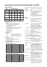
ANTENNA RADIATOR
1. Type Slotted waveguide array
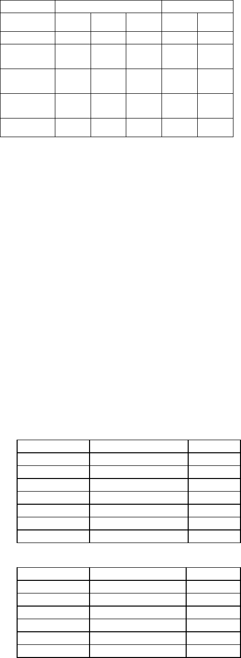
2. Beamwidth and sidelobe attenuation
X-band S-band
Radiator
Type
XN12AF XN20AF XN24AF SN30AF SN36AF
Length (mm) 1260 2040 2550 3090 3765
Beamwidth
(H)
1.8° 1.23° 0.95° 2.5° 2.1°
Beamwidth
(V)
20° 20° 20° 25° 25°
Sidelobe att.
Within ±
10
°
28 dB 28 dB 28 dB 24dB 24 dB
Sidelobe att.
Outside ±
10
°
32dB 32 dB 32dB 30 dB 30 dB
* SN30AF is available for non-SOLAS ship or for HSC
radar (FR-2135S)
3. Rotation
. FR-2115/2125/2115-B/2125-B: 24/42 rpm
. FR-2125W/2135SW/2125W-B/2135SW-B:
26 rpm (60 Hz), 21 rpm (50 Hz)
. FR-2135S/2135S-B:
26 rpm (60 Hz), 21 rpm (50Hz), 45 rpm (for HSC)
. FR-2155/2155-B: 20 rpm (DC and 60 Hz),
16 rpm (50 Hz)
. FR-2165DS: 24 rpm
RF TRANSCEIVER
1. Frequency
X-band 9410 MHz ± 30 MHz (12, 25 kW)
9415 MHz ± 30 MHz (50 kW)
S-band 3050 MHz ± 30 MHz (35, 60 kW)
2. Output power
FR-2115/2115-B : 12 kW,
FR-2125/2125W/2125-B/2125W-B: 25 kW,
FR-2155/2155-B: 50 kW
FR-2165DS: 60 kW,
FR-2135S/2135SW/2135S-B/2135SW-B: 30 kW
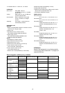
3. Pulselengths and PRR
<FR-2115/2125/2115-B/2125-B>
Range scales P/L (µs) PRR (Hz)
0.125, 0.25 0.07 3000
0.5 0.07.0.15 3000
0.75, 1.5 2 from 0.07/0.15/0.3 3000/1500
3 2 from 0.15/0.3/0.5/0.7 3000/1500
6 2 from 0.3/0.5/0.7/1.2 1500/1000
12, 24 2 from 0.5/0.7/1.2 1000/600
48, 96 1.2 600/500
<FR-2155/2125W/2135S/2135SW/2165DS/
2155-B/2125W-B/2135S-B/2135SW-B>
Range scales P/L (µs) PRR (Hz)
0.125, 0.25, 0.5 0.08 2200
0.75, 1.5 0.08/0.3* 2200/1100
3 2 from 0.08/0.3*/0.6 2200/1100
6 2 from 0.08/0.3*/0.6 2200/1100
12, 24 0.6/1.2 1100/600
48, 96 1.2 600/500
*: In case of FR-2155/2165DS/2155-B, 0.3 is replaced
with 0.2.
4. IF 60 MHz, Logarithmic. BW 28/3 MHz
5. Noise figure 6 dB
6. Duplexer Ferrite circulator with diode limiter for
FR-2115/2125/2135S/2135SW/
2115-B/2125-B/2135S-B/
2135SW-B/2165DS.
Ferrite circulator with TR limiter for
FR-2155/2155-B/2125W/2125W-B.
DISPLAY
1. Picture tube 21” multi-color, 1280 x 1024 pixels,
Rasterscan non-interlace at 61.44
kHz hor, 60 Hz vert.
Effective display diameter 275 mm
IMO type Yellow or green echoes in 16 levels.
Echoes in the same color in 16
graduation for smooth display.
Different colors for marks, legends,
alarms to ensure easy observation.
Regular type Yellow or green echoes in 16 levels
or 3 colors depending on echo
strengths
2. Minimum range and discrimination
Meets 35 m HSC requirements
3. Range scales 0.125, 0.25, 0.5, 0.75, 1.5, 3, 6, 12,24,
48, 96
Note:
Max. range for Japanese version is
FR-2115/2115-B: 72 nm, Other: 120 nm
4. Range accuracy 1% of range or 15 m, whichever is
the greater
5. Bearing discrimination Better than 2.5° except 9 ft
S-band radiator. Accuracy ±1°
6. Presentation Head-up, Head-up TB, North-up, TM
Sea or ground stabilization
7. Plotting facilities
EPA 10 targets manual plotting (standard).
Not operational in ARPA mode.
ARPA Automatic Radar Plotting Aid for 30
targets automatically or manually
acquired, dynamic and static trial
maneuver, complies with A.823(19).
Common features Sea and ground stabilized vectors
and target trails, 3 target data readout
at a time
8. Radar map Nav lines, coastlines, buoys, etc.
produced by operator as required by
IMO and IEC standards. 150 points x
10 areas stored in EEROM.
9. Guard zone 2 GZs at 3 and 6 nm in width of 0.5
nm, any sector, in ARPA mode.
10. Target alarm zone 1st zone within 3-6 nm, 2nd zone
anywhere
11. Target trails Plotted in light blue not to interfere
with radar picture, intervals 15, 30 s,
1, 3, 6, 15, 30 min, true or relative on
RM mode; true only in TM mode.