sensors, lamp circuits and the control unit.
Corrosion at the terminals may also be a
contributory cause.
8 Never short circuit a sensor supply wire or
the electronic module will be damaged.
Check control unit and monitor -
removal and refitting
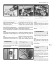
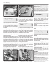
9 Remove the instrument panel as described
in Section 21.
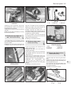
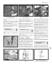
10 Unbolt the control unit housing from the
instrument panel.
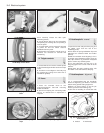
11 Access to the monitor can only be
obtained after removing the tachometer and
the red and green general warning lamps.
Unscrew the two monitor fixing bolts.
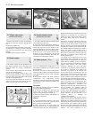
35 Clocks - setting
1
Quartz type
1 To set the hands, depress the knob and
turn it.
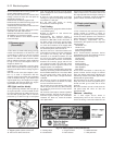
Digital type
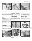
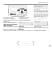
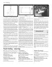
2 To set the clock, depress button A to
display minutes and seconds and again to
display hours and minutes.
3 To correct the hour setting, press button C
then button A and release it at the correct
time. Depress button C three times to display
hours and minutes.
4 To correct the minute setting, depress
button C twice. Depress button A and release
it when the correct time is shown. Depress
button C twice to display hours and minutes.
5 To correct the second setting, depress
button C three times. Depress button A and
hold it depressed to zero the seconds then
release the button. Depress button C to
display the hours and minutes.
6 Switch D, Fig. 9.16 operates the map
reading lamp fitted to SX models in
conjunction with the digital clock.
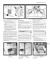
36 Cigar lighter
1
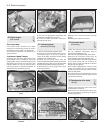
1 This device can be operated without
switching on the ignition.
2 Push in the knob and when it springs out it
is ready for use.
3 The cigar lighter socket may be used as a
power source provided the rating of the
accessory does not exceed 100 watts.
Electrical system 9•13
Fig. 9.16 Digital clock controls (Sec 35)
A Control button - hour setting C Control button - minute setting
B Control button - display (ignition off) D Map reading lamp switch
9
Fault finding overleaf


