


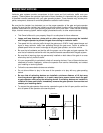
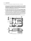
Mount operator to pad using 3/8 or 1/2 sleeve anchors.
See page 14-15.
1
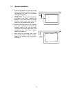
2
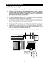
Attach chain. Adjust chain to allow approximately 1-inch of sag per 10-feet of gate width.
Be sure to remove the pin from the breather plug.
See page 16-17.
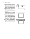
3
Connect supply voltage as described in section 2.2. Be sure power is OFF!
See page 22.
4
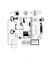
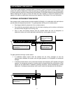
Connect control wiring as shown. Radio receiver connects to terminals 1-2-3. Full open
input devices connect to terminals 4 and 13. Partial open input devices connect to
terminals 5 and 13. Terminals 1 and 13 are the same - 24 volt common.
5
Connect secondary entrapment prevention devices.
See page 24-25.
6
Connect in-ground loop wires to REVERSE and EXIT loop detectors as required.
See page 26.
7
Set close timer ON or OFF (SW-1, switch 2) as required. If gate system does not utilize in-
ground loop system or photo-cells, timer must be OFF.
See page 34-35.
8
Push gate to open position. Adjust OPEN limit nut to activate open limit switch. Push gate
closed. Adjust CLOSE limit nut to activate close limit switch.
See page 36.
9
Turn power ON. Give gate an open command. If gate runs towards CLOSE position, turn
power off. Change setting of direction switch (SW-1, switch 1) and then turn power ON.
Give gate an open command. Adjust limit nuts as necessary.
See page 36.
10
Adjust both open and close inherent reverse sensitivity. NOTE: Operator will assume a
"soft shutdown" during sensitivity adjustments. This will require operator open input to be
activated to resume normal operation.
See page 37.
QUICK START
4