


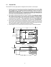
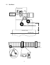

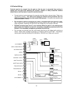
2.2 High Voltage Connections
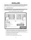
Use Table 1 to determine high voltage wire size requirements. The distance shown in the chart is
measured in feet from the operator to the power source. If power wiring is greater than the maximum
distance shown, it is recommended that a service feeder be installed. A separate power disconnect
must be installed at the operator. The wire table is based on stranded copper wire. Wire run
calculations are based on a 3% voltage drop on the power line, plus an additional 10% reduction in
distance to allow for other losses in the system.
WIRE SIZE / DISTANCE IN FEET VOLTS HP AMPS
12 AWG 10 AWG 8 AWG 6 AWG
115 1/2 5.4 170 275 460 685
208 / 230 1/2 2.7 685 1100 1830 2750
460 1/2 1.4 2875 4600 7665 11500
115 1 9.7 95 155 250 385
208 / 230 – 3
Ø
1 2.8 660 1060 1765 2650
460 – 3
Ø
1 1.3 2980 4770 8000 11940
Table 1
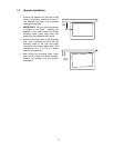
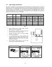
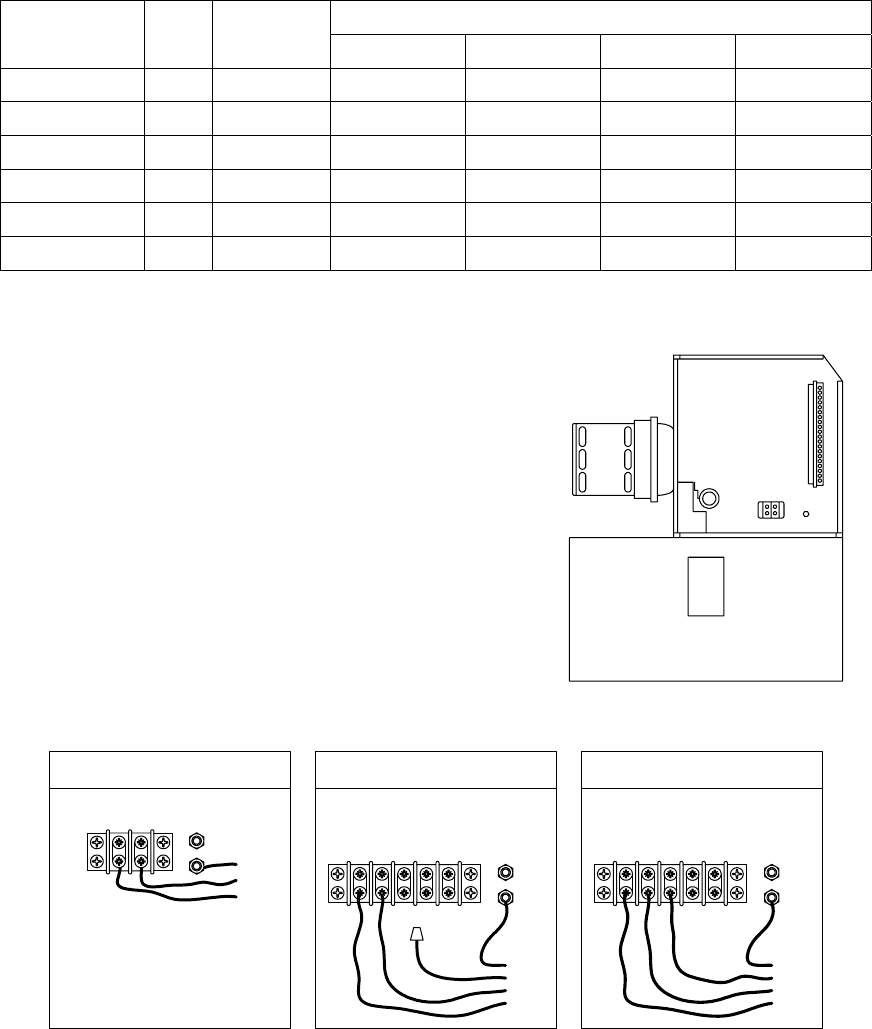
• Route incoming high voltage power through
disconnect and into the operator.
SEE DETAIL
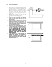
• Be sure wiring is installed in accordance with local
codes. Be sure to color code all wiring.
• Connect the power wires to the high voltage
terminal strip as shown.
• It is recommended that a surge suppresser be
installed on the high voltage power lines to help
protect the operator and circuit board from surges
and power fluctuations.
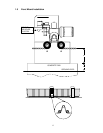
• If 3-Ph power is used to power a ½ HP unit, cap
off one leg of the power as shown below.
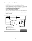
½ HP - High Voltage 3
Ø
Power
208/230/460
208/230/460
VAC 3 Ph
208/230/460
BLACK
BLACK
GREEN
BLACK
1 HP - High Voltage 3
Ø
Power
208/230/460
208/230/460
VAC 3 Ph
208/230/460
208/230/460
BLACK
BLACK
GREEN
BLACK
115 VAC
½ - 1 HP - 115 VAC Power
HOT
NEUT
BLACK
WHITE
GREEN
22