


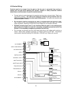
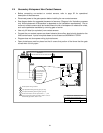
2.3 Control Wiring
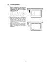
Controls must be far enough from the gate so that the user is prevented from coming in
contact with the gate while operating the controls. Outdoor or easily accessible controls
should have a security feature to prevent unauthorized use.
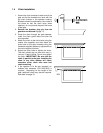
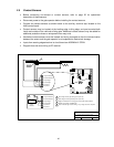
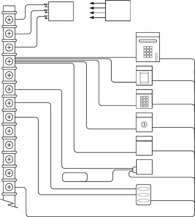
• Connect optional control devices to the operator terminal strip as shown below. Check your
connections carefully! The 4403 circuit board has different wiring terminals than the
4402 circuit board found in the older model 9300 operator. All inputs to the terminal strip
must be NORMALLY OPEN.
• Be sure that all electrical connections are made in accordance with local electrical codes.
Use 18 AWG wire for all low voltage wiring, maximum distance 3000 feet. Use a low voltage
surge suppresser, DoorKing P/N 1878-010 if low voltage wire runs exceed 1000 feet.
• Standard reversing input (term 7) only functions while the gate is in the closing cycle
and should not be used as an input for a secondary entrapment prevention device. See
Section 2.4 for secondary entrapment prevention device wiring.
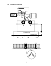
• Do not power any devices from the circuit board other than a low voltage radio receiver as
shown. Radio power available at terminal 3 is limited to 250 ma at 24 VAC. Three-button
control station must be DoorKing P/N 1200-006 or 1200-007 only. Others will not work.
24V Com
Relay
Radio Pwr
3-Wire
Receiver
To
Terminal
4-Wire
Receiver
24V Com --
Relay
Relay
Radio Pwr +
1
1
2
3
Telephone
Entry
Card Reader
Keypad
Key Switch
Fire
Dept
Fire Dept.
DoorKing
3-Button Control
External
Loop Det
Loop
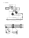
24V COMMON 1
PARTIAL OPEN 5
24V RADIO PWR 3
OPEN / RADIO RELAY 2
OPEN 4
3-BUTTON OPEN 7
3-BUTTON CLOSE 8
REVERSE / STOP 6
TRACKER DATA 9
TRACKER BUSY 10
RELAY 11
RELAY 12
24V COMMON 13
23