


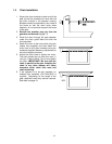

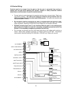
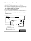
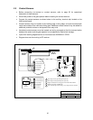
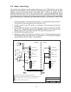
2.4 Secondary Entrapment Non-Contact Sensors
• Before connecting non-contact or contact sensors, refer to page 32 for operational
description of these sensors.
• Disconnect power to the gate operator before installing the non-contact sensors.
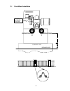
• See diagram below for suggested placement of sensors. (Diagram is for illustration purposes
only. Actual placement of the sensors is dependent on the installation requirements). One or
more non-contact sensors shall be located where the risk of entrapment or obstruction exists,
such as the perimeter reachable by a moving gate or barrier.
• Use only UL listed (or equivalent) non-contact sensors.
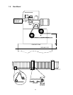
• Connect the non-contact sensors as shown below to the auxiliary terminal strip located on the
4403 control board. Inputs from photo-beam to circuit board are NORMALLY OPEN.
• Diagram does not show power wiring to photo-beams.
• Open photo-beam must be placed so that it covers that portion of the fence that the gate
covers when it is fully open.
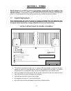
DOORKING, INC., INGLEWOOD, CA 90301
Title:
Date: Rev.Dwg. No.
Secondary Entrapment Protection Wiring
Photocells
A
9/03 M9310-065-2
1
1
4
3
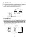
Photocell connected to reverse input terminal 7 (- - - -) will
reverse gate during CLOSE cycle if SW1, switch 7 is OFF, or
will STOP the gate if SW1, switch 7 is ON..
Photocell power wiring not shown.
1
3
Open photocell STOPS gate during open cycle only.
2
Gate
1 Open Photocell
2 Close Photocell
3 Open Edge
4 Close Edge
5 Common
6 Common
Close Beam
Open Beam
Close photocell STOPS gate during close cycle only.
2
4
24