


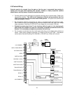
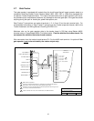
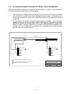
2.5 Contact Sensors
• Before connecting non-contact or contact sensors, refer to page 32 for operational
description of these sensors.
• Disconnect power to the gate operator before installing the contact sensors.
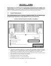
• Connect the contact sensors as shown below to the auxiliary terminal strip located on the
4403 control board.
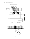
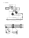
• Contact sensors may be located at the leading edge, trailing edge, and post mounted both
inside and outside of the vehicular sliding gate. Additional contact sensors may be added for
additional protection where an entrapment zone may exist.
• Hardwired contact sensors must be located and wiring arranged so that the communication
between the sensor and the gate operator is not subjected to mechanical damage.
• Inputs from sensing edges/receiver to circuit board are NORMALLY OPEN.
• Diagram does not show wiring to RF receiver.
1
1
3
Gate
1 Open Photocell
2 Close Photocell
3 Open Edge
4 Close Edge
5 Common
6 Common
2
3
Edges connected to the moving gate can be made wireless with the
addition of an RF Kit, P/N 8060-061.
1
3
Open edge reverses gate during open cycle only.
2
Close edge reverses gate during close cycle only.
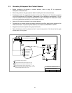
1 Open Photocell
2 Close Photocell
3 Open Edge
4 Close Edge
5 Common
6 Common
24 VAC Power
Relay
Common
Edge
Receiver
DOORKING, INC., INGLEWOOD, CA 90301
Title:
Date: Rev.Dwg. No.
Secondary Entrapment Protection Wiring
Contact Sensors
A
9/03 M9310-065-3
4
4
Non-monitored edge receiver wiring. Only a single receiver is required.
25