


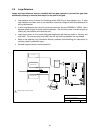
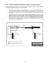

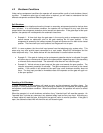

3.2 Switch Settings
The two DIP-switches located on the circuit board are used to program the operator to operate in
various modes and to turn on or off various operating features. Whenever a switch setting is
changed, power to the operator must be turned OFF and then turned back on for the new setting to
take affect. Check and review ALL switch settings prior to applying power to the operator.
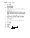
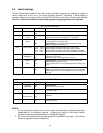
SW 1 (UPPER SWITCH)
SWITCH FUNCTION SETTING DESCRIPTION
1 Direction OFF
ON
Changes open / close direction of operator.
2 Auto Close
Timer
OFF
ON
Auto-close timer is OFF. Manual input required to close gate.
Auto-close timer is ON. Adjustable from 1-23 seconds.
3 Open Loop
Output
OFF
ON
Switches logic-level output of EXIT loop port to terminal 4 and
removes terminal 4 as an open input.
Normal Setting. Control board responds internally to loop
detector plugged into exit loop port.
4 & 5 Relay & LED 4-OFF 5-OFF
4-OFF 5-ON
4-ON 5-OFF
4-ON 5-ON
Relay activated and LED on when gate is FULL OPEN.
Relay activated and LED on when gate is NOT CLOSED.
Relay activated and LED on when gate is OPENING and OPEN.
Relay activated and LED on when gate is OPENING or CLOSING.
6 Solenoid Lock
(see note 1)
OFF
ON
Normal setting. Fail-safe logic. Lock engages only if attempt is
made to force gate open.
Fail-secure logic. Lock engages after each cycle.
7 Reverse
Stop
OFF
ON
Normal Setting. Input to terminal 6 or reverse detector will
REVERSE gate during close cycle.
Input to terminal 6 will or reverse detector STOP gate during close
cycle.
8 Timer Override OFF
ON
Normal Gate Operation.
Opening gate will stop and begin to close as soon as all reversing
inputs (loops, beams) are clear regardless of the open position of
the gate.
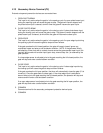
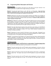
SW 2 (LOWER SWITCH)
SWITCH FUNCTION SETTING DESCRIPTION
1 Self Test
(see note 2)
OFF
ON
Normal setting.
Run self-test – bench test only.
2 Open Uphill OFF
ON
Level – Normal Setting.
Gate opens uphill.
3 Slide Gate
Overhead Gate
OFF
ON
Normal setting. Must be in the OFF position for slide gate
operators.
4 Close Uphill OFF
ON
Level – Normal Setting.
Gate closes uphill.
NOTES:
1. Do not change the setting of this switch unless the solenoid/lock assembly has been
repositioned for the operation desired. Changing the setting of this switch without
physically changing the lock assembly will damage the operator.
2. Do not run the self-test while the gate operator is connected to the gate. This self-test
feature is designed for bench-testing only.
34