


SECTION 3 - ADJUSTMENTS
The switch settings and adjustments in this chapter should be made after your installation and wiring
to the operator(s) is complete. Whenever any of the programming switches on the circuit board are
changed, power must be shut-off, and then turned back on for the new setting to take effect.
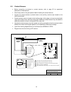
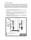
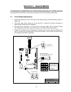
3.1 Circuit Board Adjustments
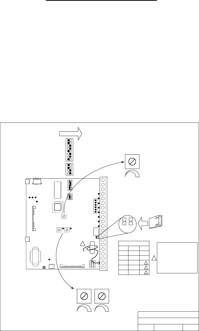
• Set the DIP-switches on the circuit board to the desired setting. See switch-setting charts in
section 3.2.
• Auto close timer (when turned on) can be set from 1 second (full counter clockwise) to
approximately 23 seconds (full clockwise).
• Dry contact relay (terminals 11-12) can be set for Normally Open (NO) or Normally Closed
(NC) operation by placing the relay shorting bar on the NO or NC pins respectively.
• Power LED indicates that low voltage power is applied to the circuit board. Input LEDs should
be OFF and will only illuminate when the input is activated. The limit LED will be ON when
the respective limit switch is activated.
Relay Contact Setting
NO - Relay Normally Open (factory)
NC - Relay Normally Closed
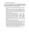
REVERSE SENSOR
MIN MAX
MIN MAX
CLOSE OPEN
1
2
3
4
1
2
3
4
5
6
7
8
SW1 SW2
ON
DOORKING, INC., INGLEWOOD, CA 90301
Title:
Date: Rev.Dwg. No.
4403 Control Board Adjustments
B
5/05 M9310-065-8
NC
NO
CAUTION
HIGH VOLTAGE
TIMER
MIN MAX
0 - 23 Seconds
SW1, Switch 4 ON
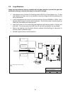
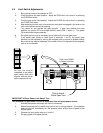
1
Current Sensor Donut
½ HP All 2
1 HP 115 / 1 1
Motor Volt/Ph Turns
1 HP 208 / 3 5
1
1 HP 230 / 3 5
1
1 HP 460 / 3 9
1
1
For 1 HP 3
Ø
motors, connect
red sensor wire directly to lug
opposite terminal 19. Route
black motor wire directly
through current sensor donut.
See wire diagram:
4403-1-202346-3
33