


12
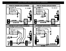
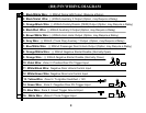
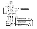
VIOLET WIRE: (+) DOOR TRIGGER
Connect to Positive type door switches that show +12 Volts when the door is open and Ground when the doors are closed.
WHITE/BLACK WIRE: DOOR UNLOCK CONTROL INPUT
Connect Door Unlock input from aftermarket switch. This is a negative Door Unlock input that controls the onboard relay for
Power Door Unlock output wire.
WHITE/GREEN WIRE: DOOR LOCK CONTROL INPUT
Connect Door Lock input from aftermarket switch. This is a negative Door Lock input that controls the onboard relay for the
Power Door Lock output wire.
YELLOW WIRE: IGNITION SWITCHED “ON” and “START” +12 VOLTS
Connect to a (+) Ignition wire that shows +12 Volts when the key is in both the “ON” and “Cranking” positions.
GREEN WIRE: (-) DOOR TRIGGER
Connect to Negative type door switches that read ground when a door is opened and 12 volts when all doors are closed. In
the case of isolated door triggers, you may need to run additional wires from other doors OR go directly to the dome light.
BLUE WIRE:(-) HOOD TRIGGER
The Blue wire is used for a grounding hood pin switch. Connect to existing pin switches that read ground when open. If no
existing switches are available, install new pin switches if desired. Note: DO NOT mount new pin switches in water pathways
WHITE: (-) TRUNK PIN SWITCH INPUT
Input trigger for a grounding trunk pin switch. Connect to existing trunk pin switches that read ground when open. If no
existing switches are available, install new pin switches if desired. Note: DO NOT mount new pin switches in water
pathways.