


10
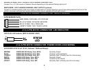
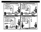
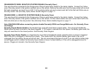
ORANGE/WHITE WIRE: NEGATIVE STARTER DISABLE (Normally Open)
This wire should be connected to the Orange wire of the pre-wired relay socket for the starter disable. Connect the Yellow
wire of the relay socket to the Ignition switched wire on the vehicle. Remove the white wire from the relay socket with a small
flat head screwdriver an insert it in pin # 87. Cut the vehicle starter wire and connect each half to the Red and White wire on
the relay socket. See (Normally Open) Starter disable diagram on page 11.
ORANGE WIRE: (-) NEGATIVE STARTER DISABLE (Normally Close)
This wire should be connected to the Orange wire of the pre-wired relay socket for the starter disable. Connect the Yellow
wire of the relay socket to the Ignition switched wire on the vehicle. Cut the vehicle starter wire and connect each half to the
Red and white wire on the relay socket. See (Normally Close) Starter disable diagram on page 11.
Note: READ BELOW before connecting starter disable! Normally OPEN use Orange/White wire. For Normally Close
use Orange.
Normally Closed Starter disable is the standard type used with most alarm systems today. This circuit will disable the
Starter while the alarm is armed or has been triggered. If 12V power is removed from the system, the Battery goes dead; the
relay will revert back to the closed position. See Normally Close Diagram.
Normally Open Starter Disable is a High-Security circuit that will disable the starter while the alarm is armed or triggered
AND if the unit is unplugged or removed from power. This means that if the vehicle’s Battery goes dead or the unit is
unplugged from the vehicle, the car will still not start. We only recommend this type of circuit if you can install a hidden high-
current toggle switch to defeat the Normally Open disable in case of a dead battery or if the unit is unplugged/remove for
service. (Toggle not included) See Normally Open Diagram.