


MOUNTING THE COMPONENTS
1. Mounting The Siren Control Module
Select a flat, metal surface within the engine compartment, but noton
theengine,formountingthesirencontrolmodule.Keepinmindthatthe
horn end must be facing down to prevent water from entering the
module.
A location on the firewall, which is not easily accessible from under-
neath the vehicle, is preferred. This location will provide optimum
operation of the shock sensor, and prevent the potential thief from
disconnecting the alarm from below the vehicle.
You should also locate the control module away from hot or moving
components within the engine compartment, and avoid areas where
water will run off or collect during heavy rainstorms.
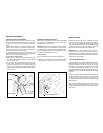
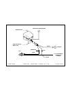
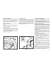
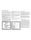
To mount the siren control module;
A. Secure themodule mounting bracket to the selectedlocation using
the(2) 3/4"long screwsprovided. Carefullydrill a1/8"diameter pilot
hole for starting the screws.
B. In most cases, if the bracket has been secured to a solid metal
surface, you can connect the BLACK wire from the wiring harness
to thesiren mounting bolt.Using a10 mm wrenchor socket, secure
thesirenmodule (andeyeletterminalontheend oftheBLACKwire)
tothe bracketusingthe (2)3/8"long hexheadboltsand (2)splitlock
washers provided.
2. Mounting The Dash L.E.D. Indicator
Selectan areaon thedashboard orcenterconsole thatwill providethe
most visibility from all angles outside the vehicle ( driver’s window,
passenger’s window, rear window, etc. ).
IMPORTANT !Make sure thereis adequateroom for thebody ofthe
L.E.D. behind the panel in the selected location. You should also be
sure that the drill will not pierce any wires, or damage other compo-
nents afterpassing throughthe panel.It isalways bestto removethe
panel from the vehicle before drilling the hole.
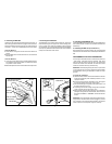
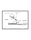
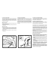
To mount the L.E.D.;
A. Drill a 1/4" diameter hole at the selected mounting location.
B. Pass the L.E.D. wires through the hole from the front of the panel,
and press the body of the L.E.D. into the hole until fully seated.
WIRING THE SYSTEM
Making the connections to the vehicle, as described in this wiring
section, may be beyond the technical abilities of the average con-
sumer. If you have any questions with the wiring procedures, please
callaqualifiedautomotivetechnician,orcalltheAUDIOVOXHOTLINE
at 1-800 -225 -6074. Priorto makingany connections,a 12 Voltlogic
probe should be used to confirm the proper connection point.
IMPORTANT ! The 4 pin white connector on the end of the main
harness that plugs into the siren control module should remain
disconnectedduring thewiringportion oftheinstallation. Leavingthis
disconnected will ensure that the keychain transmitters are properly
programmed later in the installation.
1. Routing The Wiring Harness
The DARKBLUEwire mustbe routedthrough thefirewall, andinto the
passenger compartment of the vehicle, towards the dash L.E.D. In
most cases, the RED wire will also be routed into the passenger
compartment, to the courtesy light fuse. Before proceeding with the
wire routing, verify the location of the courtesy light fuse, as a small
percentageof vehicleslocatethisfuse intheengine compartment,and
in these cases, it will not be necessary to route the RED wire through
the firewall.
After confirming these component locations, route the DARK BLUE
and RED wires towards their connection points. Caution should be
used when routing wires. Keep wires away from all hot surfaces, and
any moving parts of the vehicle ( radiator fans, accelerator or brake
pedal linkage, etc. ).
When routing wires through the firewall, be sure to pass the wires
through an existing rubber grommet. Failure to do this can result in
damagetowires fromsharpmetaledges,andan eventualfailureofthe
security system.
Page 1
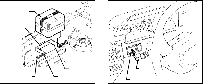
BRACKET
SIREN MODULE
3/8" LG. HEX BOLTS
SPLIT LOCKWASHER
3/4" LG. SCREWS
L.E.D.
DRILL A 1/4" DIAMETER HOLE