


7
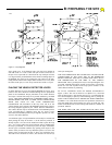
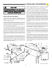
above grade. Two 13/32 diameter holes will need to be drilled on
each side of the 4 x 4 tube. Center each pair of holes on the face of
the post 2-5/8” apart and 7/8” down from the top. Each pair of holes
is to align with the pre-drilled holes in the chassis mounting angles of
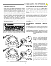
the RS4000. See Figure 6 for locating the post relative to the gate,
noting that the center of the output shaft is located 4 5/8” away from
the center of the post, or 2 5/8” away from the face of the 4 x 4 post.
PLACING THE VEHICLE DETECTOR LOOPS
If vehicle detectors are to be used with the RS4000, the "loops" to be
buried in the drive should be installed during the site preparation
phase of the installation. Proper placement of the vehicle detector
wire loops is critical if the loops are to provide satisfactory, extended
service. THE MOST IMPORTANT CONSIDERATIONS ARE: 1)
PROPER WIRE TYPE AND, 2) GOOD, TIGHT CONNECTIONS
FROM THE LOOP TO THE LOOP TERMINATING
CONNECTOR. The termination of the loop wires will be at the
vehicle detector itself, and not at the RS4000 terminal panel. Observe
the wiring diagram supplied by the vehicle detector manufacturer.
The vehicle detector may be mounted inside of the RS4000 operator
cover, provided there is adequate room. The AC power service
delivered to the RS4000 operator may be tapped to provide 115 VAC
service to the vehicle detector.
Two different types of loop installations will usually be encountered
when placing the loops in the drive: 1) If the driveway material is
already in place. saw cuts will be needed in which to place the loop
wire. 2) For loops where the paving material will be installed after
the loop is positioned, it is necessary to place the loops in Schedule
40 PVC pipe to maintain uniform loop spacing with respect to the
surface of the pavement. The loop should be placed 1.5" below the
surface of the pavement and at least 2" above any reinforcing steel.
The lead-in wires need not be in PVC, but must have at least six (6)
twists per running foot.
THE LOOP WIRES MUST BE CONTINUOUS. NO SPLICES OR
CONNECTIONS IN THE LOOP ARE TO BE PERMITTED
BELOW GROUND. THE ONLY CONNECTION WILL BE AT
THE TERMINATION OF THE WIRE AT THE VEHICLE
DETECTOR. Above ground splices may be used providing the wire
is twisted, soldered and moisture sealed. For best long term results,
do not use wire nuts anywhere in the loop system. Connect to the
vehicle detector harness by soldering.
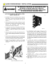
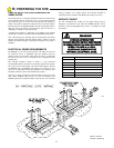
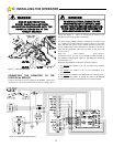
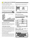
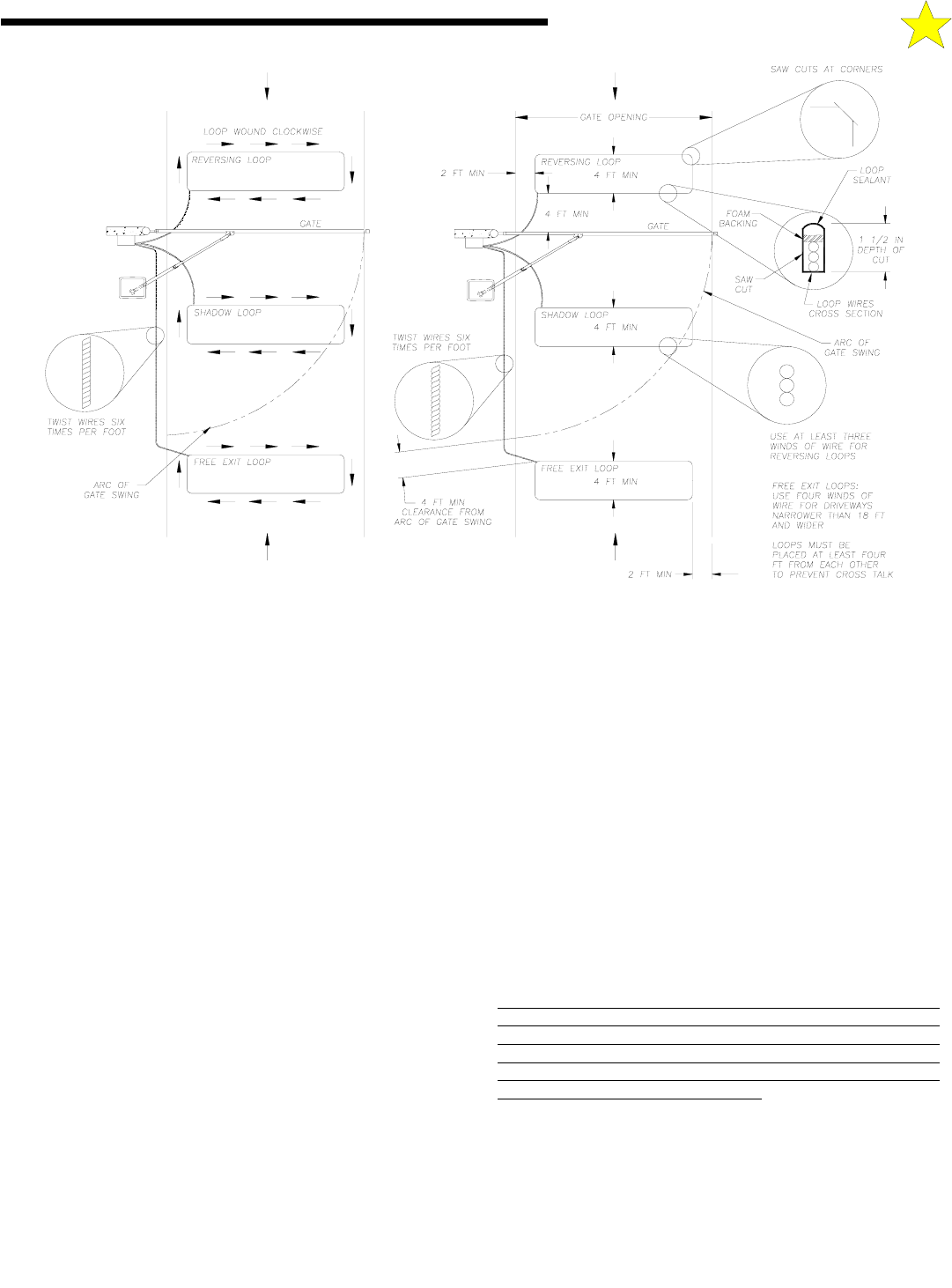
For saw-cut installations, observe the methods recommended in
Figure 7, above. The saw-cut must be to a depth of 1.5", clean and
with no sharp corners. After placing the wires, it is essential that the
wires be held tightly in place by a foam backing prior to pouring the
sealant. THIS IS ESPECIALLY IMPORTANT WHEN FREEZING
IS LIKELY. No voids should exist that will permit the collection of
water that might freeze and push the loop wires out of the slot. The
sealant used should not be hard setting and should be suitable for
pavement material.
THE WIRE USED FOR THE LOOPS MUST BE HEAT AND
WATER RESISTANT, CROSS-LINK POLYETHYLENE
INSULATED. TYPE XLPE IS BEST. RHW IS O.K. DO NOT USE
ANY PVC INSULATED WIRE. (PVC insulation will absorb
moisture that may affect Detector operation.) WIRE SIZE SHOULD
BE #16 GA. STRANDED OR LARGER.
IN
OUT
IN
OUT
Figure 7: Loop Diagrams
106508
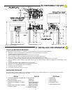
B: PREPARING THE SITE