


11
INSTALLING THE GATE ARM KIT
The gate arm kit can be installed on the RS4000 only after the
operator has been properly and securely installed, and the correct
gate/operator geometry relationship has been established and
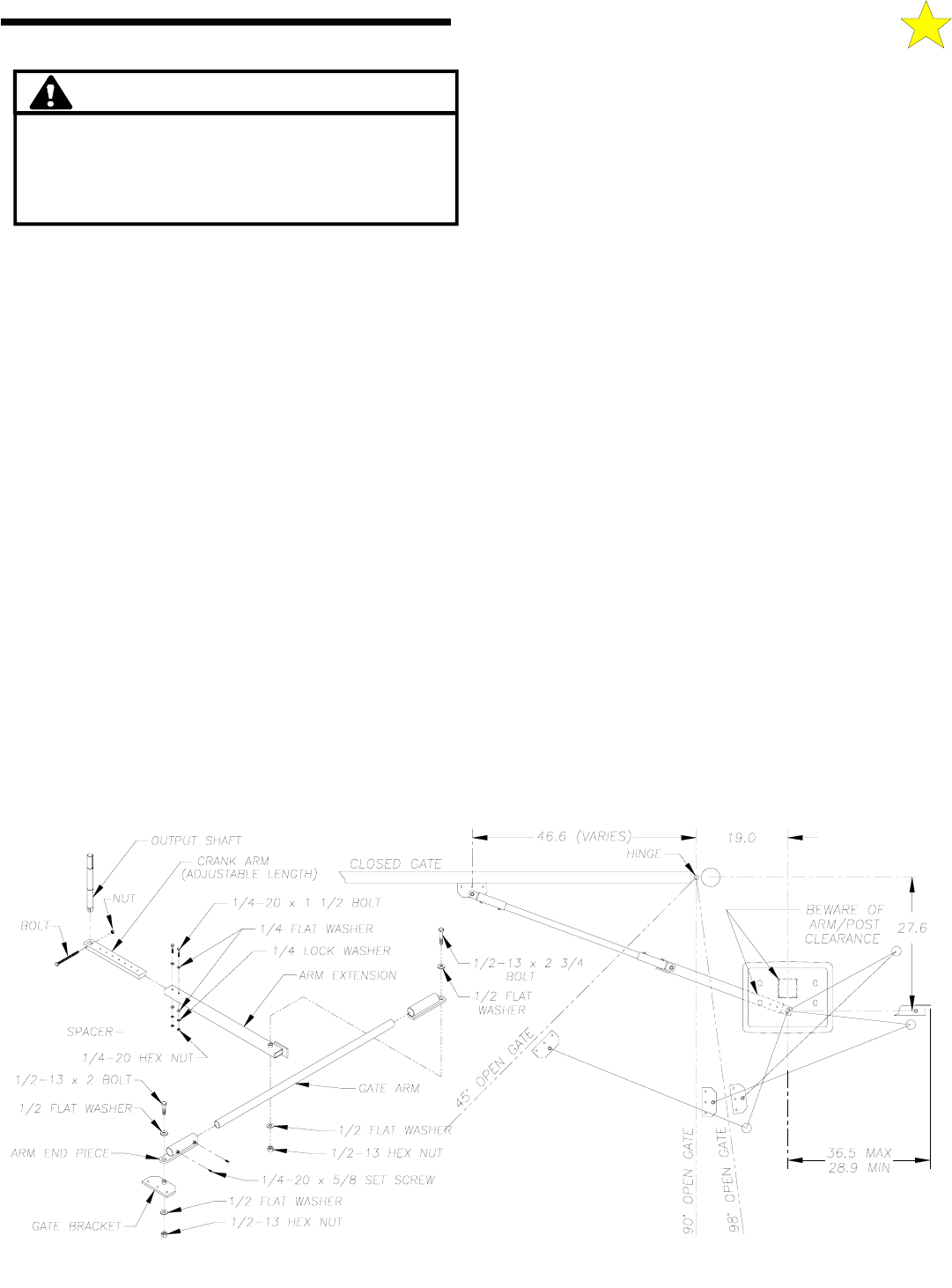
verified. (See Figures 6 and 10.)
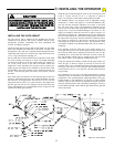
Locate the crank arm in the gate arm kit and install it on the output
shaft of the RS4000 at the underside of the chassis, oriented so the
through hole in the crank arm is aligned with the through hole in the
output shaft. The crank arm is secured to the output shaft with a 5/16-
18 x 2” long bolt and nylon stopping nut.
Get the crank arm extension from the arm kit and slide it on the crank
arm. This assembly can telescope to various arm lengths depending
on which pair of holes is used. Six length settings are possible: 33-
3/8, 31-7/8, 30-3/8, 28-7/8, 27-3/8 and 25-7/8 inches. Choose the
length that is most appropriate for the gate system. Typically, the
longer the gate, the longer the arm should be to provide more stable
gate handling. Secure the extension to the crank arm with the two
1/4-20 x 1-1/2 inch long bolts, flat washers, lock washers, and nuts
provided.
Next, install a gate arm end piece at each end of the pipe as shown in
Figure 10. The length of this arm is also variable depending on where
the end pieces are snugged down with the four 5/16-18 x 5/8 inch
long square head set screws (two, each end piece). The length of the
gate arm pipe may also be cut to length to suit the needs of the gate
system, although this is not recommended, because a longer arm will
promote more stable gate operation.
Install the gate bracket through the eyelet of the arm end piece and
secure it in place with the 1/2-13 x 2” long bolt as shown in
Figurez10, using the two flat washers and Nylok nut provided.
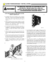
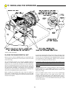
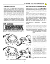
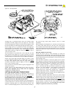
The RS4000 operator was designed with an Adjustable Torque
Output Drive. (“ATD”) (See Figure 9.) For initial installation of the
gate arm, the drive should be adjusted to zero torque, so the crank
arm will swing freely. This is accomplished by loosening (do not
remove) the two reducer-slide clamp bolts on each side of the shaft
support tower. To prevent accidental damage to the limits, etc., the
trigger pin should be removed at this time as shown in Figure 18.
The tension on the flat poly-v adjustable torque drive belt can now be
relieved a small amount at a time until the large pulley installed on
the output shaft will just slip when the crank arm is manually rotated.
The tension is increased or decreased by turning the cap-nutted
tensioning bolts as shown in Figure 9. Note: The capnuts have been
permanently installed on the threaded shank and will not loosen or
un-thread).
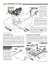
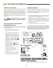
Next, manually swing the crank arm to the position shown for a
closed gate in Figure 10. Now install the gate arm pipe assembly on
the end of the crank arm by dropping the end piece eyelet over the
protruding sleeve of the crank arm extension, as shown. Swing the
gate arm assembly around until it is straight in line with the crank
arm, and the “elbow” is up against the closed position stop.
Swing this locked arm assembly around until the gate bracket just
meets the gate as shown in Figure 10. Elevate or lower the arm
assembly until it is level, and then temporarily clamp the gate bracket
to the gate. The “elbow” pivot of the gate arm assembly should be
secured with the 1/2-13 x 2-3/4” long bolt, with flat washers and lock
nut, provided.
Now manually move the gate to the fully opened position, moving
cautiously at first, to ensure there is no interference between gate arm
components or the operator/pedestal. Slight adjustments to the gate
bracket location or arm length may be necessary to ensure smooth
operation. Make several trial runs by manually moving the gate from
closed to opened positions, until a smoothly operating gate system is
assured. When satisfied, weld or bolt the gate bracket to the gate and
remove the clamps.
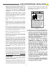
TO PREVENT DAMAGE TO THE LIMITS, ETC.,
DURING INSTALLATION OF THE GATE ARM,
REMOVE THE LIMIT TRIGGER PIN PRIOR TO
INSTALLING THE GATE ARM
CAUTION!
106511
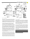
Figure 10: Arm Positions
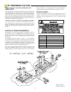
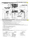
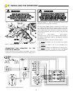
C: INSTALLING THE OPERATOR