


13
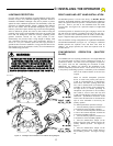
LIGHTNING PROTECTION
For areas where a high probability of ground lightning strikes exists
(Florida, Georgia, etc.,) additional lightning protection should be
installed in the RS4000. Although it may not be possible to protect
against all strikes, additional protection will substantially reduce the
occurrence of lightning damage. Allstar’s lightning data indicates
that the most strikes enter the RS4000 through the power lines.
Effective protection requires that the surge current from the lightning
strike be shunted to ground. This must be done without raising the
potential of the circuitry in the RS4000, with respect to ground, to the
levels that will damage the solid state circuitry. Lightning strikes
generate enormous currents for very short periods of time.
Unfortunately, the period of time is long enough to damage solid
state components and many times, other components. The key to
success is a very low resistance path from the surge protector to
ground for these currents in addition to a surge protector that will act
fast enough to protect the solid state circuitry. Several manufacturers
offer suitable surge protectors.
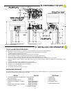
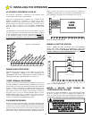
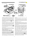
RIGHT HAND AND LEFT HAND INSTALLATION
The RS4000 operator is wired at the factory for RIGHT HAND
operation. Right hand operation is described as the gate swinging in
and to the right and where the operator is mounted to the right of the
gate leaf - both as you look at the installation from the inside
(secured side). See Figure 4 for a pictorial example of a right hand
operation.
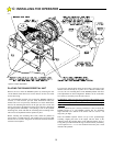
Left hand operation is described as the gate swinging in and to the
left and where the operator is mounted to the left of the gate leaf -
both as you look at the installation from the inside (secured side).
Figure 7 diagrams depict gates and operators in a left hand set-up.
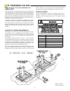
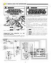
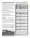
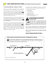
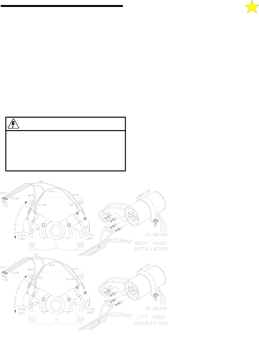
Note the different wiring configurations for right-hand installations
and left-hand installations (see Figure 13). To change to a different
handed operation the capacitor wires and limit wires must be
changed. For proper operation, the limits and capacitor must be
wired as shown.
SYNCHRONOUS OPERATION (MASTER/
SLAVE)
Two RS4000 units in a bi-parting situation (one wired right-hand and
one wired left hand, see above) can be configured to operate in a
synchronous manner. The units can be wired together to operate as
one system, with one unit controlling the movement of both.
Additionally, the installer can customize the installation of the
external entrapment protection devices. These devices can be wired
to the primary (controlling) operator or alternately to the individual
units as the situation dictates or the end user
requires.
When an external entrapment protection
device is wired to the primary unit (such as
would be recommended for a photoelectric
beam across the entire opening) both units
will react to the detection of an obstruction,
regardless of the location of the obstruction.
An edge device (or similar) protecting an
entrapment zone particular to the secondary
unit could be wired to that unit only and
would react individually to the detection of an
obstruction. Synchronous movement would
resume once the obstruction is cleared and an
open or close command is received by the
primary operator.
To obtain synchronous operation (5 Steps):
1. Wire the Primary Operator Terminal #14
to Terminal #6 in the Secondary Operator.
2. Wire the Common Operator Terminal #0
or #16 to the Common Operator Terminal #0
or 16 in the Secondary Operator.
3. Wire the Primary Operator Terminal #15
to Terminal #7 in the Secondary Operator.
4. Place the Master/Slave Jumper on the
Primary Operator motor control board to the
primary (Master) position. See Figure 19,
Page 18.
5. Place the Master/Slave Jumper on the
Secondary Operator motor control board to
the secondary position. See Figure 19, Page
18.
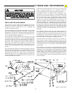
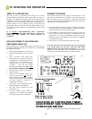
C: INSTALLING THE OPERATOR
WARNING!
TO REDUCE THE RISK OF DAMAGE DUE TO
LIGHTNING, ENSURE A SOLID GROUND
FROM THE TWIST’R GROUND WIRE IN THE
SERVICE ENTRANCE 2 x 4 HANDY BOX TO
THE ELECTRICAL SERVICE GROUND OR TO A
EARTH GROUND STAKE NEAR THE TWIST’R.
106515 REV D
Figure 13: Left/Right Hand Installation Limit & Motor Wiring Diagram