


16
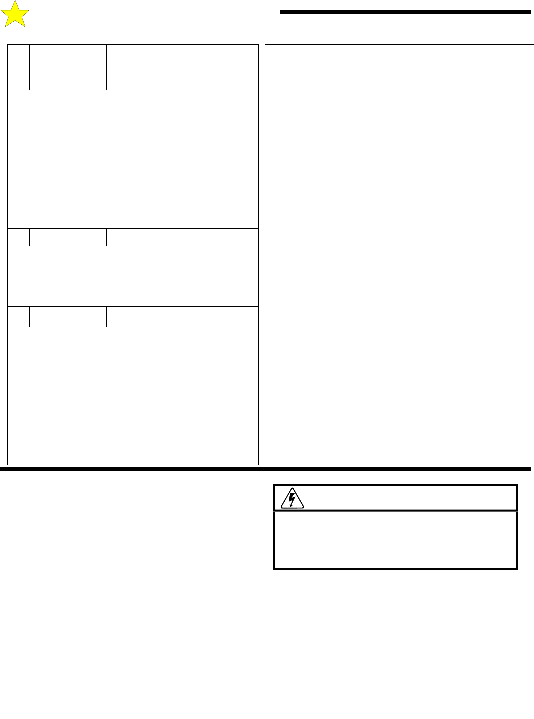
TERMINAL STRIP REFERENCE CHART
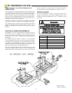
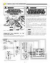
D: STARTING THE OPERATOR
# NAME
DESCRIPTION
13 CLOSE EDGE
Momentary or continuous signal.
This input is active only when referenced to the closing direction, it
has no effect on the gate when opening or about to open. If
activated when the gate is closing the gate will stop, pause and
reverse in the open direction for 1/2 second (approx. 2 inches) and
stop. Continuous activation will prevent the gate from moving in
the close direction. Continuous activation while the gate is open
will prevent the Timer-To-Close function (if enabled) from
automatically closing the gate. If a second activation occurs before
the limit switch is activated the gate will stop and a require a
renewed, intended input to move in the close direction and before
an automatic activation device (timer, etc.) will operate. This input
is intended for Electric Gate Edge systems and other minimum-
contact devices as appropriate. Connect here and to terminal #16
COMMON. Multiple devices may be connected in parallel.
14 MASTER OPEN
Momentary or continuous signal. Master
(output configuration)
This terminal is used to coordinate two independent systems (two
control box/mechanical unit combinations controlling separate gate
leaves). Connects to terminal #6 (OPEN) in the companion control
box and controls the direction of movement in the companion box
(Switch Jumper Position diagram, Figure 19, Page 18).
15 MASTER CLOSE
Momentary or continuous signal. Master
(output configuration)
16 COMMON
Common connection for low voltage
signal inputs, terminals 2 through 15.
This terminal is used to coordinate two independent systems (two
control box/mechanical unit combinations controlling separate gate
leaves).Connects to terminal #7 (CLOSE) in the companion control
box and controls the direction of movement in the companion box
(Switch Jumper Position diagram, Figure 19, Page 18).
#
NAME
DESCRIPTION
10 CLOSE PHOTO
Momentary or continuous signal.
This input is active only when referenced to the closing
direction, it has no effect on the gate when opening or about to
open. If activated when the gate is closing the gate will stop,
pause and reverse in the open direction for 1/2 second
(approx. 2 inches) and stop. Continuous activation will
prevent the gate from moving in the close direction. When the
input is removed normal operation is resumed. . Continuous
activation while the gate is open will prevent the Timer-To-
Close function (if enabled) from automatically closing the gate.
This input is intended for photoelectric eye systems and other
non-contact devices as appropriate. Connect here and to
terminal #16 COMMON. Multiple devices may be connected
in parallel.
11 REV LOOP
Momentary or continuous signal.
This input is active only when the gate is closing or when it’s
fully open and the Close Timer is operative. All stand-alone
vehicle detectors, photo-eyes and active edges should be
connected here and to terminals #3 or #13 COMMON.
Multiple devices may be connected in parallel.
12 OPEN EDGE
Momentary or continuous signal.
This input is active only when referenced to the opening
direction, it has no effect on the gate when closing or about to
close. If activated when the gate is opening the gate will stop,
pause and reverse in the close direction for 1/2 second
(approx. 2 inches) and stop. Continuous activation will prevent
the gate from moving in the open direction. If a second
activation occurs before the limit switch is activated the gate
will stop and a require a renewed, intended input to move in
the open direction and before an automatic activation device
(timer, etc.) will operate. This input is intended for Electric
Gate Edge systems and other minimum-contact devices as
appropriate. Connect here and to terminal #16 COMMON.
Multiple devices may be connected in parallel.
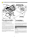
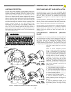
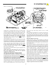
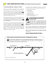
SETTING THE LIMIT SWITCHES
Once the gate arm has been installed to the gate and operator, the
limit switches can be adjusted and set. BE CERTAIN TO TURN
THE MAIN POWER SWITCH TO THE OPERATOR “OFF”
BEFORE PROCEEDING.
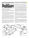
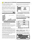
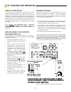
The instructions in this manual describe a right hand gate installation,
as shown in Figure 10. A right hand gate installation is defined as a
gate which swings inward and to the right to an open position, with
the operator on the right, as viewed from inside of the gate area
facing out. The RS4000 as shipped is configured for a right hand
installation. If a left hand installation is required, the limit switch
wires and motor wires must be swapped. This is fully defined in the
right hand/left hand wiring schematic illustrated in Figure 13.
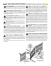
Assuming a right hand gate installation, swing the gate to position it a
few inches short of the fully closed position. In this right hand
installation, the “closed” gate limit will be located on the left side of
the output shaft (see Figure 18).
The limit mechanism consists of a spring loaded flipper toggle which
activates a micro switch. These are installed on a bracket which
pivots around the output shaft. A trigger pin, installed on the large
output pulley, is used to flip the toggle and thus activate or de-
activate the micro switch. With this mechanical combination, the
switching action is positive and precise. This accuracy is not
diminished by repeated operations of the gate.
Identify the small trigger pin mounting hole closest to the “close”
limit located toward the front
side of the pulley between the “open”
and “close” limit brackets. Manually swing the gate open until this
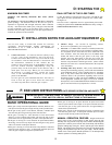
WARNING!
RISK OF ELECTROCUTION
DO NOT BEGIN TO SET THE FOLLOWING
ADJUSTMENTS UNTIL THE POWER IS
TURNED OFF AT THE TWIST’R CONTROL BOX