


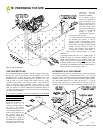
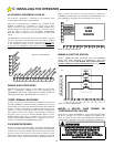
6
THE CONCRETE PAD
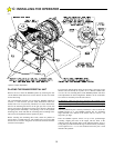
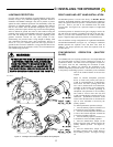
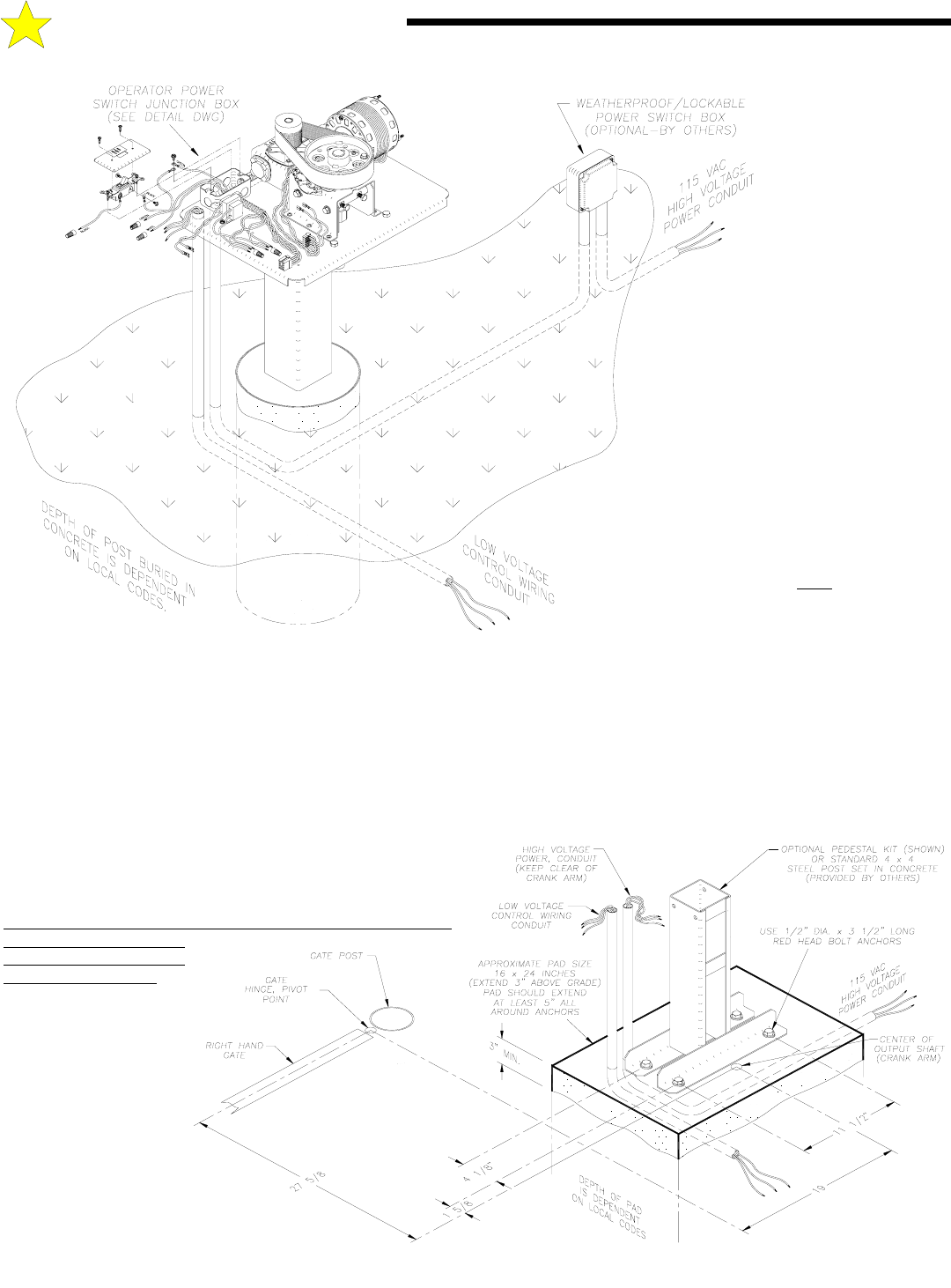
The standard RS4000 is designed to operate a single leaf gate. Bi-
parting gate systems are possible with the addition of a second
RS4000 operator. (Consult the factory.) Each RS4000 has its own
dedicated control board contained within the operator cover. Care
must be taken to provide separate high voltage and low voltage
conduits to each operator. (See Figures 5 and 6.) Care must also be
taken in choosing proper placement of the conduit to avoid
interference with the swinging crank arm which connects to the output
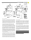
shaft. See Figure 8A for basic dimensions and guidelines. Figure 10
illustrates the full sweeping area which the crank arm will encompass
in a typical gate installation.
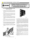
If the optional pedestal kit is used, the Installation of the RS4000
Mechanical Unit will
require a suitable concrete
pad as a mounting base. The
dimensions of the concrete
pad should be sufficient to
allow at least 5" of
clearance from each edge of
the pad to the nearest
pedestal mounting hole. The
top of the pad should be at
least 3" above grade to raise
the operator above any
standing water. The depth of
the pad below grade is
dependent on the weight and
size of the gate and the soil
conditions at the site of the
installation. ALWAYS
FOLLOW LOCAL
BUILDING CODES.
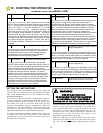
If no suitable concrete
base exists, a pad must be
poured. See Figurez6 for
plans for this pad. If the
location of the operator is
such that vehicles have
the potential of hitting the
operator, consideration
should be given to
installation of protective
posts in front of the operator.
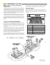
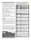
If a suitable concrete base already exists
for mounting the operator it will be
necessary to drill mounting holes for the
RS4000 operator. 3/4" mounting holes are
located on the front and rear of the optional
pedestal. The bolt pattern is shown in
Figurez6. The mounting bolts should be
1/2" diameter or larger. "Red head" or
wedge anchor concrete bolts are usually
satisfactory.
If mounting anchor bolts are to be installed prior to
pouring the pad, pay particular attention to the bolt
pattern and the location of the mounting holes with
respect to the center line of the gate hinge
. It is critical for
the proper operation of the Arm that the center line of the
output shaft of the RS4000 operator be located exactly as
shown on the bolt pattern drawing, Figure 6.
ALTERNATE 4 X 4 POST MOUNT
The RS4000 operator offers an alternative to the optional pedestal kit
for mounting installation. A standard architectural 4 x 4 x 1/8 wall
steel tube may be substituted for the pedestal and installed in a similar
manner to a fence post: Dig a hole of proper diameter (approximately
12”) and suitable depth per local codes, and set the 4ZxZ4 post in
concrete. Make sure the post is plumb and level. The top of the post
should be cut off clean and square and should extend at least 18”
B: PREPARING THE SITE
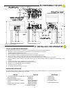
Figure 5: Pad Configuration
106505
Figure 6: Operator Footprint
106506