


17
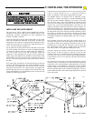
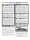
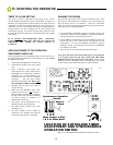
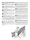
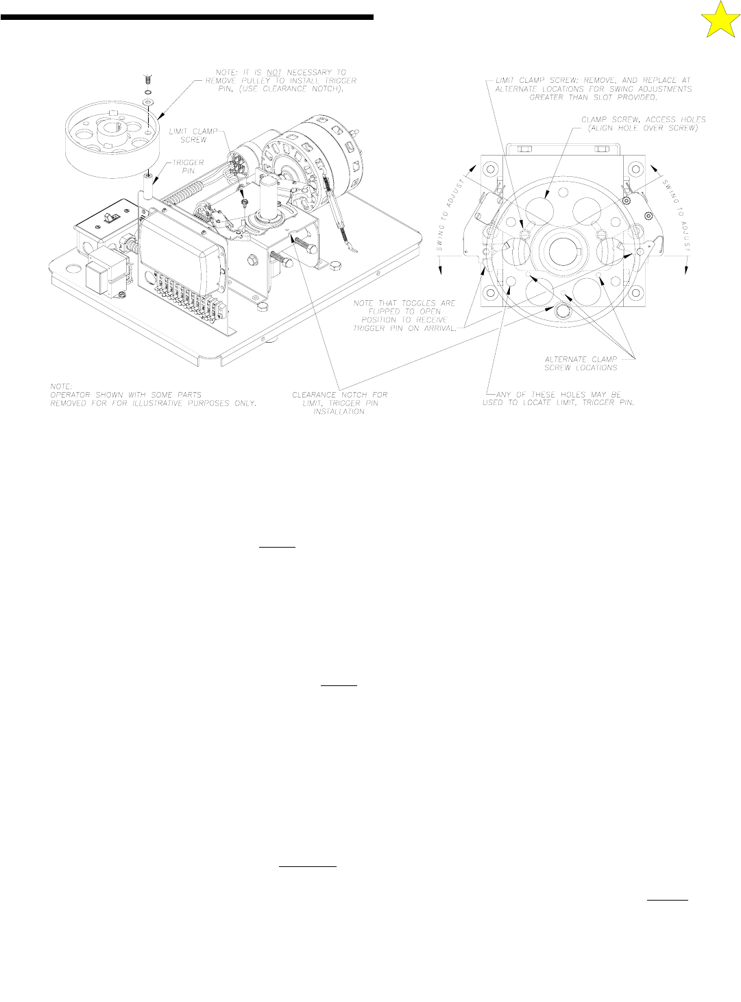
mounting hole is positioned directly above the clearance notch
provided in the shaft support tower (see Figure 18). This notch
provides the appropriate clearance to install the limit trigger pin with
the bolt and washers provided. Install the trigger pin firmly in place.
Flip the toggle open so it is positioned to receive the trigger pin.
Swing the gate to a position that is just a few inches short of the fully
closed position. Now swing the “close” limit bracket
around the
output shaft toward the trigger pin until the toggle just trips to
“close” the micro switch.
The limit brackets are provided with a slot so that they can slide
freely about the limit clamp screw. It may be necessary to relocate
this clamp screw to bring this slot within the range of the trigger pin.
Alternate clamp screw locations have been provided for this purpose.
Flip the “open” limit toggle toward the trigger pin so that it is ready
to receive. Manually swing the gate to a position that is just short of
the fully “open” position. Now swing the “open” limit bracket
around the output shaft toward the trigger pin until the toggle just
trips to “close” the micro switch.
Lock the positions of the limit brackets by gently snugging the limit
clamp screws in place.
NOTE: These are the rough settings for the “open” and “close”
limits. Final adjustment will be made after the Adjustable
Torque Drive system has been set.
SETTING ADJUSTABLE TORQUE DRIVE
The RS4000 operator incorporates an Adjustable Torque Drive to
limit the amount of force that the gate arm can exert. This provides
the additional flexibility to fine tune the output of the gate system
.
BEFORE BEGINNING THIS PROCESS, BE SURE THE MAIN
POWER SWITCH TO THE OPERATOR IS
OFF.
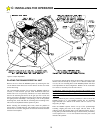
Output torque can be increased by turning the belt tensioning bolts in
a clockwise direction. To decrease torque, reduce the belt tension by
turning the tensioning bolts in a counter-clockwise direction. This
allows a controlled slipping action to occur between the flat Poly-V
belt and the large output pulley, similar to that of a clutch
mechanism.
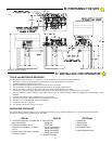
Before turning the tensioning bolts, it is necessary to loosen the four
(4) reducer slide clamp bolts (two each side of the shaft support
tower), and the motor mount clamp nut (see Figure 9). Loosening the
motor mount clamp nut allows the motor/pulley to pivot. Gravity will
tension the V-Belt as the reducer slide moves in and out of the shaft
support tower.
BE SURE POWER IS STILL OFF!
Tension the Poly-V belt by small increments by turning the
tensioning bolts as a balanced pair. After tensioning the Poly-V belt,
test the grip between the belt and drive pulley by applying manual
pressure against the gate and estimating the resistance by the operator
before slipping occurs.
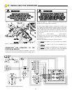
When the desired resistance is achieved, tighten the four reducer
slide clamp bolts. Evaluate the motor drive belt tension by applying a
moderate downward pressure on the belt midway between the two
pulleys. If an excessive amount of deflection occurs, loosen the
clamp nut slightly and apply a slight downward pressure to the
motor. The motor drive belt can be further tensioned by turning
the body nut of the turnbuckle. Turn clockwise to increase belt
tension. Do not over tension. This turnbuckle will also help to
maintain motor belt tension and facilitate easy re-adjustment
should the belt stretch with age. Re-tighten the motor clamp nut.
Additional adjustments may be necessary after the RS4000 operator
has been powered up and is fully operable.
Now that the Adjustable Torque Drive has been set, limit settings
obtained in the previous section must be fine tuned. Move the limit
brackets a degree at time while cycling the operator. Note the gate’s
actual stopping position. Continue to adjust the limit brackets
by very
small increments while cycling the operator until the exact stopping
position desired is reached. Lock the limit brackets in place by
snugging the limit clamp screws. Test and adjust the Torque Drive
setting on a regular basis (at least once per month).
D: STARTING THE
106512
Figure 18: Limit Adjustments