


14
ACCESSORY EQUIPMENT HOOK-UP
All accessory equipment is connected to the terminal strips
located on the control panel of the RS4000.
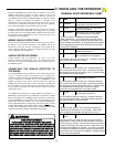
There are 11 command inputs available to the installer on the
RS4000 in addition to 2 commons. To trigger any of these
inputs, a switch or relay closure to the common terminal for a
duration longer than 100 milliseconds and of a resistance of less
than 100 ohms is necessary. See the INPUT COMMANDS
Reference Chart on Pagez16 for an explanation of each of the
inputs.
The RS4000 has a transformer mounted on the chassis to power
accessory equipment. The maximum power that can be supplied
by this transformer is 5VA or about 1/4 Ampere at 24VAC
. This
is only intended to supply power to a radio receiver. A Separate
power supply is required for loop detectors or card or key pads.
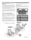
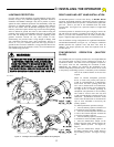
WIRING RADIO RECEIVERS
Radio Receivers may be either 3 wire (terminal) or 4 wire units.
THE 3 TERMINAL VERSION OF THE RECEIVER IS
PREFERRED SINCE NO ADDITIONAL CONNECTIONS TO
THE RECEIVER WILL BE REQUIRED. See Figure 15.
THREE TERMINAL RECEIVERS
If a three wire receiver is to be used, the #1 terminal of the receiver is
normally COMMON to both the auxiliary transformer (power input)
and the radio relay. Most radio manufacturers label this terminal as
24 VAC. Connect a wire from the #1 terminal of the radio receiver to
terminal #1. The #2 terminal of the radio receiver is normally the
relay contact of the receiver. Connect a wire from this #2 terminal of
the radio receiver to the #2 terminal (RADIO RELAY) of the
RS4000 control panel. The #3 terminal of the radio receiver is
usually labeled RADIO POWER and is connected to 24 VAC.
Connect to terminal #3 of the RS4000 control panel.
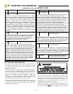
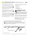
FOUR WIRE RECEIVERS
Four wire receivers replace the "spade" terminals on the RECEIVER
with 4 wires. These wires are typically color coded. The instructions
with the receiver must be carefully followed to properly connect the
receiver. For any 4 wire receiver, two of the wires will be for power
input and two will be for the relay contacts. Connect the two wires
for the power input to each side of the 24VAC RS4000 terminals #1
and #3. Connect one of the two wires for the relay to terminal #1
(COMMON) and the other wire to terminal #2 (RADIO RELAY) on
the terminal strip. See Figure 16 for connecting 4 wire receivers.
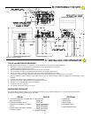
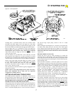
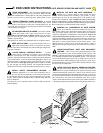
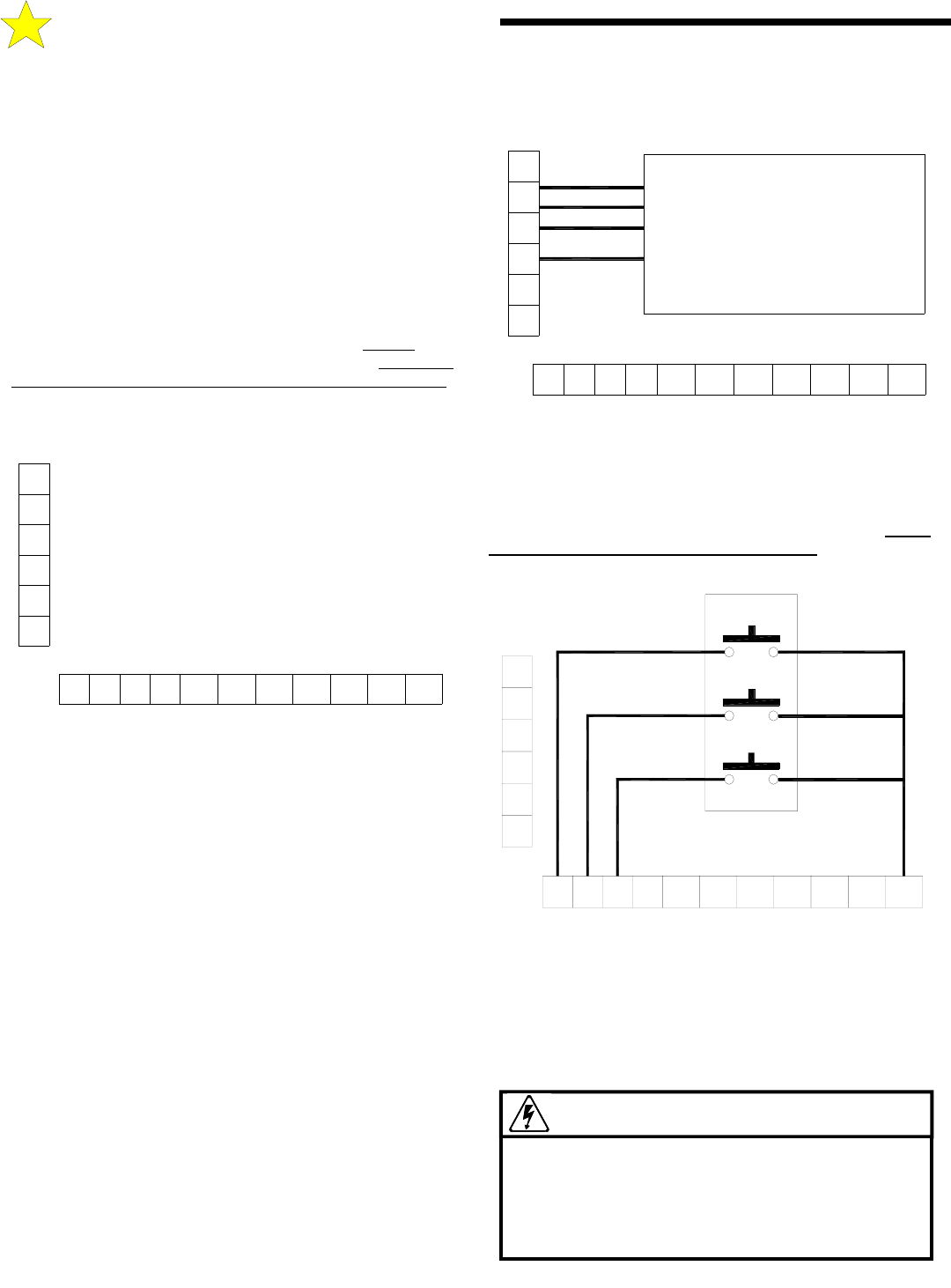
WIRING A 3-BUTTON STATION
NOTE: THREE BUTTON STATIONS MAY BE ORDERED
WITH THE STOP BUTTON AS NORMALLY OPEN OR
NORMALLY CLOSED. THE RS4000 WILL OPERATE ONLY
WITH A NORMALLY OPEN STOP BUTTON. See Figure 17 for
instructions on wiring a three button station.
WIRING A KEYPAD, CARD READER OR
TELEPHONE ENTRY SYSTEM
These devices activate the RS4000 by a relay contact closure within
the device. Typically, two wires or terminals are provided by the
device to operate the gate. Follow the manufacturers instructions on
locating these connections. If one of the connections at the device is
WARNING!
IMPROPER WIRING COULD CAUSE
ELECTROCUTION OR DAMAGE TO
CIRCUITRY. FOLLOW ALL LOCAL
ELECTRICAL CODES OR THE NATIONAL
ELECTRICAL CODE.
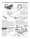
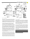
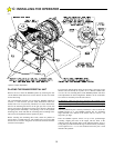
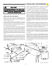
C: INSTALLING THE OPERATOR
0
1
2
3
4
5
678910
11 12
13
14
15
16
RED (POWER)
BLACK (RELAY)
BLACK (RELAY)
WHITE (POWER)
RADIO
RECEIVER
4-WIRE
110473
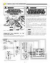
Figure 16: Wiring 4-Wire Receiver
0
1
2
3
4
5
678910
11 12
13
14
15 16
O
P
E
N
C
O
M
M
O
N
C
L
O
S
E
S
T
O
P
S
H
A
D
O
W
L
O
O
P
C
L
O
S
E
P
H
O
T
O
C
E
L
L
R
E
V
E
R
S
I
N
G
L
O
O
P
O
P
E
N
E
D
G
E
C
L
O
S
E
E
D
G
E
M
A
S
T
E
R
O
P
E
N
M
A
S
T
E
R
C
L
O
S
E
F
R
E
E
E
XI
T
R
A
D
I
O
O
P
E
N
2
4
V
A
C
A
L
T
E
R
N
A
T
E
2
4 V
A
C
C
O
M
M
O
N
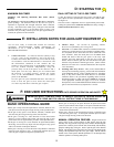
Figure 14: Terminal Strips
110472
0
1
2
3
4
5
678910
11 12
13
14
15
16
OPEN
CLOSE
STOP
Figure 17: Wiring 3-Button Station
110477