


12
CONNECTING THE OPERATOR TO THE
ELECTRICAL SERVICE
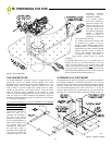
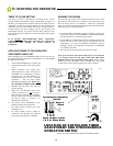
It will be necessary to run two conduits to the RS4000. One will be
used for the A-C power lines and another for the low voltage, class 2
wiring. See Figure 8. There are cutouts on the bottom of the
Operator Chassis to accept these two conduits.
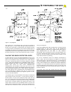
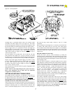
The high voltage RS4000 electrical connections are made at the
2zxz4 handy box located inside the operator at the rear, left corner
along with the main power switch. Conduit should be run from the
service breaker panel to this junction box as discussed in Section B,
along with the appropriate AWG wire (see Table 1). The color code
for 115 VAC is:
black = hot white = neutral green = ground
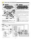
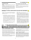
Connections for the 115 VAC service should be made according to
the schematic wiring diagram, Figure 12, and handy box illustration
shown in Figure 11.
Starting at the RS4000 2 x 4 handy box proceed as follows:
1. The BLACK
wire attaches to the 115 VAC HOT wire, normally
black.
2. The WHITE wire attaches to the 115 VAC NEUTRAL wire,
normally white.
3. The GREEN wire attaches to the GROUND wire, normally green.
It is good electrical practice to ground the frame of the RS4000
operator and is required by National and/or local electrical codes.
TO AVOID ELECTRICAL DAMAGE TO THE
OPERATOR DO NOT ALLOW TOTAL WIRE
LENGTH FROM THE SERVICE BREAKER PANEL
TO THE TWIST’R OPERATOR TO EXCEED THE
WIRE LENGTH GIVEN IN TABLEZ1, PAGE 8.
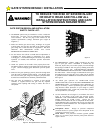
WARNING!
RISK OF ELECTROCUTION.
DO NOT BEGIN THE ELECTRICAL
CONNECTION PROCEDURES UNTIL THE
POWER IS TURNED OFF AT THE
CIRCUIT BREAKER
WARNING!
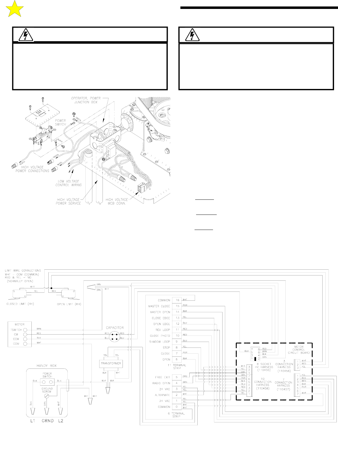
C: INSTALLING THE OPERATOR
110454 REV B
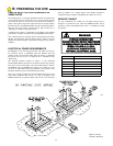
Figure 12: Schematic & Wiring Diagram
Figure 11: Handy Box Illustration
106507